Buck-Boost DC Converter

A technology of DC converter and compression type, which is applied in the direction of converting DC power input to DC power output, output power conversion devices, instruments, etc., which can solve problems such as unstable output power and affecting load operation, and reduce output ripple Effect

Active Publication Date: 2020-02-04
ALLIS ELECTRIC +1
View PDF4 Cites 0 Cited by
  • Summary
  • Abstract
  • Description
  • Claims
  • Application Information

AI Technical Summary

Problems solved by technology

[0004] Although figure 1 The buck-boost DC converter shown in the prior art has the characteristics of simple circuit and low cost, but its output power has high ripples that make the output power unstable, which in turn affects the operation of the load connected to its rear end

Method used


Image

  • Buck-Boost DC Converter
  • Buck-Boost DC Converter
  • Buck-Boost DC Converter

Examples


Embodiment Construction

[0051] Below in conjunction with accompanying drawing, structural principle and working principle of the present invention are specifically described:

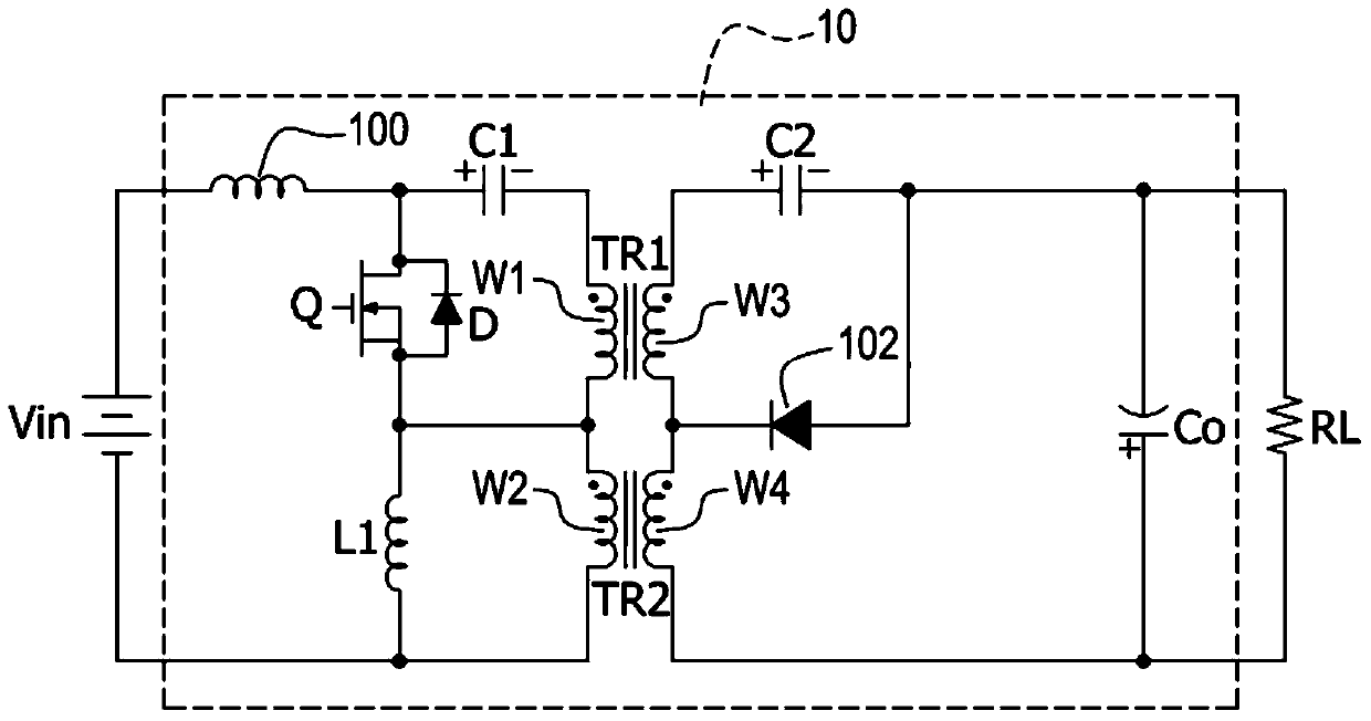
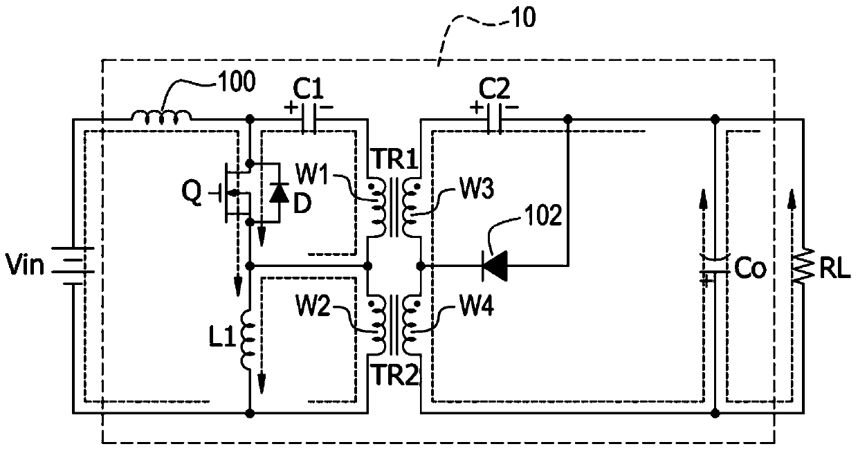
[0052] Cooperate with reference figure 2 , which is a circuit diagram of a buck-boost DC converter according to the first embodiment of the present invention. The buck-boost DC converter 10 is connected between the power supply Vin and the load RL, and includes a power isolation and conversion unit (not otherwise labeled), a ripple elimination inductor 100, a power switch Q, a first inductor L1, and a rectification element 102. The first capacitor C1, the second capacitor C2, and the output capacitor Co.

[0053] The power isolation and conversion unit contains multiple coils, such as figure 2 The electrical energy isolation and conversion unit shown includes first to fourth coils W1-W4; wherein, the first coil W1 and the second coil W2 are connected in series and located on the side where the buck-boost DC converter 10 is...


PUM


Abstract

The invention relates to a buck-boost DC converter which can achieve a characteristic of zero-ripple voltage, wherein the zero-ripple voltage represents extremely low ripple voltage close to zero in engineering. The buck-boost DC converter comprises a ripple elimination inductor, an electric energy isolation and conversion unit, a power switch, a first inductor, a first capacitor, a second capacitor and a rectifying element, wherein the electric energy isolation and conversion unit is electrically connected to the ripple elimination inductor and comprises a plurality of coils, and the coils divide the buck-boost DC converter into an input stage and an output stage; the power switch, the first inductor and the first capacitor are located at the input stage and electrically connected to the electric energy isolation and conversion unit and the second capacitor and the rectifying element are located at the output stage and electrically connected to the electric energy isolation and conversion unit.

Description

technical field [0001] The invention relates to a buck-boost converter, in particular to a buck-boost DC converter. Background technique [0002] With the rapid development of the consumer electronics market, portable electronic products are constantly changing to miniaturization and light weight, and the smaller the size of the product, the smaller the volume and capacity of the battery. This requires improving the conversion efficiency of the power supply module of such products as much as possible, reducing power consumption, and enabling it to provide a stable output voltage within a wide range of battery voltage variations, so as to prolong the battery life. Buck-boost converters capable of operating over a wide input range are widely used in such applications. [0003] Please refer to figure 1 , which is a circuit diagram of a buck-boost DC converter in the prior art. exist figure 1 Among them, the buck-boost DC converter is connected between the power source Vin a...

Claims


Application Information

Patent Timeline
Patent Type & Authority Patents(China)
IPC IPC(8): H02M3/335H02M1/14
CPCH02M1/14H02M3/33523
Inventor 潘晴财郑明杰赖炎生
Owner ALLIS ELECTRIC
Why Eureka
Try Eureka