Control circuit and method for buck-boost power supply converter
A technology for power converters and control circuits, applied in control/regulation systems, output power conversion devices, instruments, etc., can solve the problems of discontinuous duty cycle, short duty cycle, large output ripple, etc.
- Summary
- Abstract
- Description
- Claims
- Application Information
AI Technical Summary
Problems solved by technology
Method used
Image
Examples
Embodiment Construction
[0210] The present invention will be further described below in conjunction with embodiment and accompanying drawing.
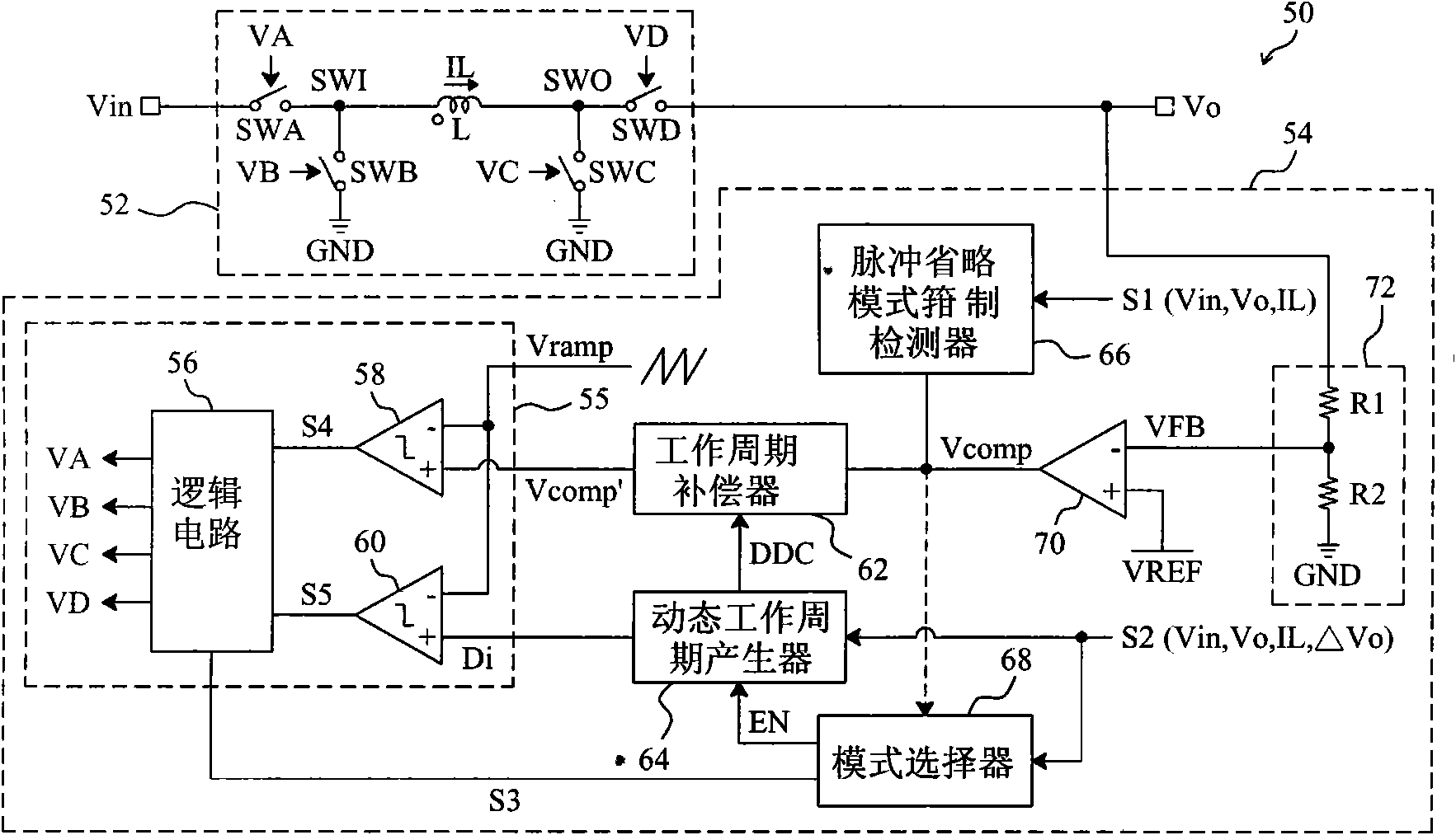
[0211] see now image 3 , image 3 A schematic diagram of an embodiment of the invention is shown. As shown in the figure, in the buck-boost power converter 50, the control circuit 54 provides control signals VA, VB, VC and VD to switch the switches SWA, SWB, and SWC and SWD are used to convert the input voltage Vin to the output voltage Vo. In the control circuit 54, the feedback circuit 72 detects the output voltage Vo to generate a feedback signal VFB, the error amplifier 70 amplifies the difference between the feedback signal VFB and the reference voltage VREF to generate an error signal Vcomp, and the pulse omission mode clamps the detector 66 clamps the level of the error signal Vcomp according to the detection signal S1, wherein the detection signal S1 is related to at least one of the input voltage Vin, the output voltage Vo and the inductor curren...
PUM
 Abstract
Description
Claims
Application Information
 - R&D
- Intellectual Property
- Life Sciences
- Materials
- Tech Scout
- Unparalleled Data Quality
- Higher Quality Content
- 60% Fewer Hallucinations
Browse by: Latest US Patents, China's latest patents, Technical Efficacy Thesaurus, Application Domain, Technology Topic, Popular Technical Reports.
© 2025 PatSnap. All rights reserved.Legal|Privacy policy|Modern Slavery Act Transparency Statement|Sitemap|About US| Contact US: help@patsnap.com


