Push-pull type electric transducer with zero voltage switch and its switching method

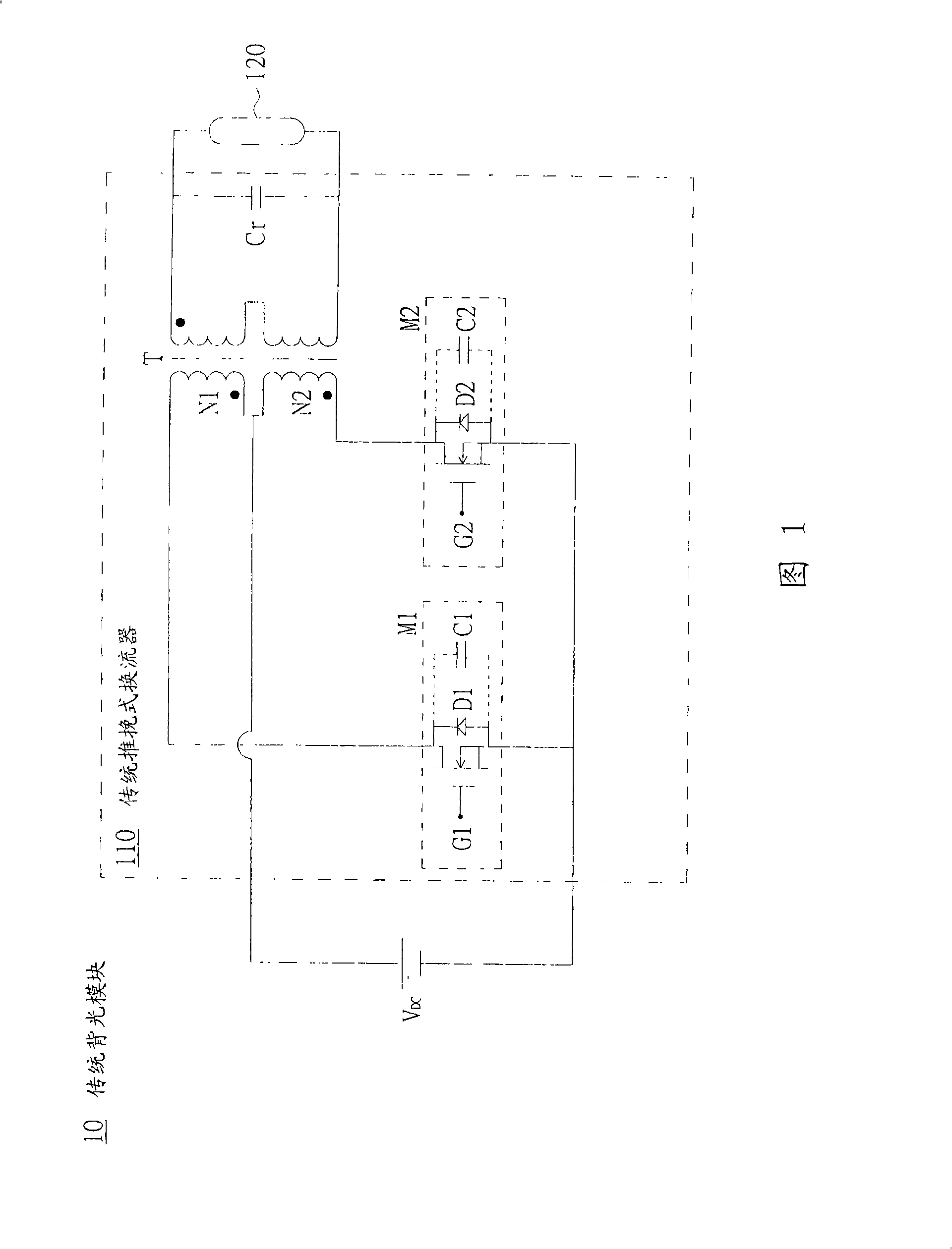
A voltage and transformer technology, applied in the field of push-pull converters, can solve the problem that the conversion efficiency of the push-pull converter 110 cannot be effectively improved, etc.

Inactive Publication Date: 2008-09-24
INNOLUX CORP
View PDF0 Cites 6 Cited by
  • Summary
  • Abstract
  • Description
  • Claims
  • Application Information

AI Technical Summary

Problems solved by technology

[0005] However, since the conventional push-pull converter 110 is at the switching instant, the switches M1 and M2 are not working in the zero voltage switching (Zero Voltage Switching) state, therefore, when the c

Method used


Image

  • Push-pull type electric transducer with zero voltage switch and its switching method
  • Push-pull type electric transducer with zero voltage switch and its switching method
  • Push-pull type electric transducer with zero voltage switch and its switching method

Examples


Embodiment Construction

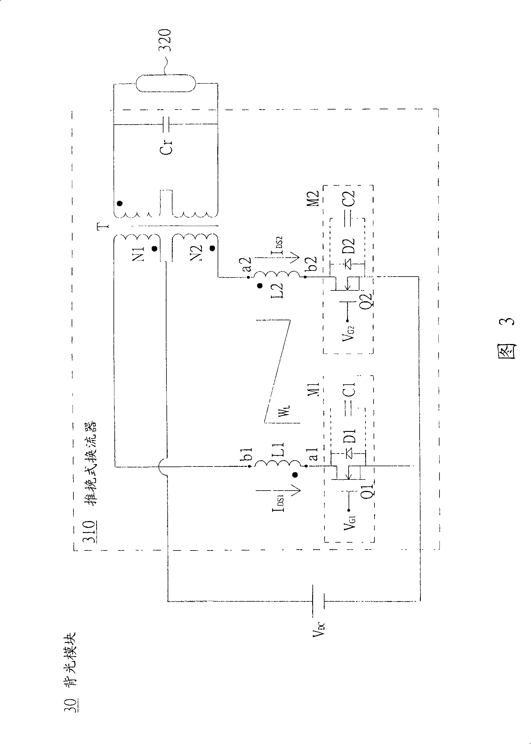
[0044]The push-pull converter alternately switches the first switch and the second switch respectively according to a first control signal and a second control signal, so as to generate an AC voltage to the transformer, so that the transformer drives the light-emitting component according to the AC voltage. In order to improve the switching loss of the traditional push-pull converter, the following embodiments use the charging and discharging characteristics of the inductor and the energy coupling characteristics, so that the first switch and the second switch of the push-pull converter work at zero voltage switching (Zero Voltage Switching) state.

[0045] In other words, the following embodiments utilize the charging and discharging characteristics of the inductor and the characteristics of energy coupling, so that the voltage at both ends of the first switch and the second switch before the first switch and the second switch are turned from off (Off) to on (On) That is, it ...


PUM


Abstract

The invention relates to a push-pull type inverter and a drive method thereof. The push-pull type inverter comprises a transformer, a first inductance, a second inductance, a first switch and a second switch. The primary side of the transformer is provided with a first winding and a second winding. The first switch and the second switch are alternatively accessed according to a first control signal and a second control signal. After the first switch is accessed, the first inductance, the first switch, the first winding and a DC power supply form a first series loop; while after the second switch is accessed, the second inductance, the second switch, the second winding and the DC power supply form a second series loop. When the first control signal is changed from an enabling level into an unable level, the first inductance couples energy to the second inductance to lead the voltages at the two ends of the second switch to be reduced to a second voltage from a first voltage before a second control signal achieves an enabling level.

Description

technical field [0001] The invention relates to a push-pull converter, and in particular to a push-pull converter with zero-voltage switching. Background technique [0002] Please refer to FIG. 1 , which shows a circuit diagram of a conventional backlight module. The conventional backlight module 10 includes a conventional push-pull inverter 110 (Push-Pull Inverter) and a cold cathode fluorescent lamp 120 (Cold Cathode Fluorescent Lamp, CCFL). The conventional push-pull inverter 110 is used to drive CCFL tubes 120 . The conventional push-pull converter 110 includes a transformer T, a switch M1 , a switch M2 and a resonant capacitor Cr. [0003] The transformer T has a primary side and a secondary side. The primary side of the transformer T has windings N1 and N2, and the windings N1 and N2 are coupled to the DC power supply V DC positive end. The switches M1 and M2 are coupled to the DC power supply V DC negative terminal. And the switches M1 and M2 are coupled to the...

Claims


Application Information

Patent Timeline
IPC IPC(8): H02M7/538H05B41/28H05B41/288
CPCY02B70/1491Y02B70/10
Inventor 陈世明李永龙
Owner INNOLUX CORP
Why Eureka
Try Eureka