Eureka AIR delivers breakthrough ideas for toughest innovation challenges, trusted by R&D personnel around the world.

Control circuit and relevant switching type voltage stabilizer

A technology for control circuits and voltage regulators, applied in control/regulation systems, output power conversion devices, instruments, etc., can solve problems such as reducing the energy conversion efficiency of buck-boost converters and increasing switching losses.

Inactive Publication Date: 2013-11-13
RICHTEK TECH
View PDF4 Cites 6 Cited by
  • Summary
  • Abstract
  • Description
  • Claims
  • Application Information

AI Technical Summary

Problems solved by technology

In the buck-boost mode, the four power switches in the switching regulator will be turned on and off alternately, which increases the switching loss of the circuit, thus reducing the energy conversion of the buck-boost converter efficiency

Method used


Image

  • Control circuit and relevant switching type voltage stabilizer
  • Control circuit and relevant switching type voltage stabilizer
  • Control circuit and relevant switching type voltage stabilizer

Examples


Embodiment Construction

[0014] Embodiments of the present invention will be described below in conjunction with related drawings. In these drawings, the same reference numerals indicate the same or similar elements or process steps.

[0015] Certain terms are used in the specification and following claims to refer to particular elements. Those skilled in the art should understand that the same element may be called by different terms. This description and the subsequent claims do not use the difference in name as the way to distinguish components, but the difference in function of the components as the basis for distinction. "Includes" mentioned throughout the specification and subsequent claims is an open-ended term, so it should be interpreted as "including but not limited to...". In addition, the term "coupled" herein includes any direct and indirect means of connection. Therefore, if it is described that a first element is coupled to a second element, it means that the first element can be dir...


PUM


Abstract

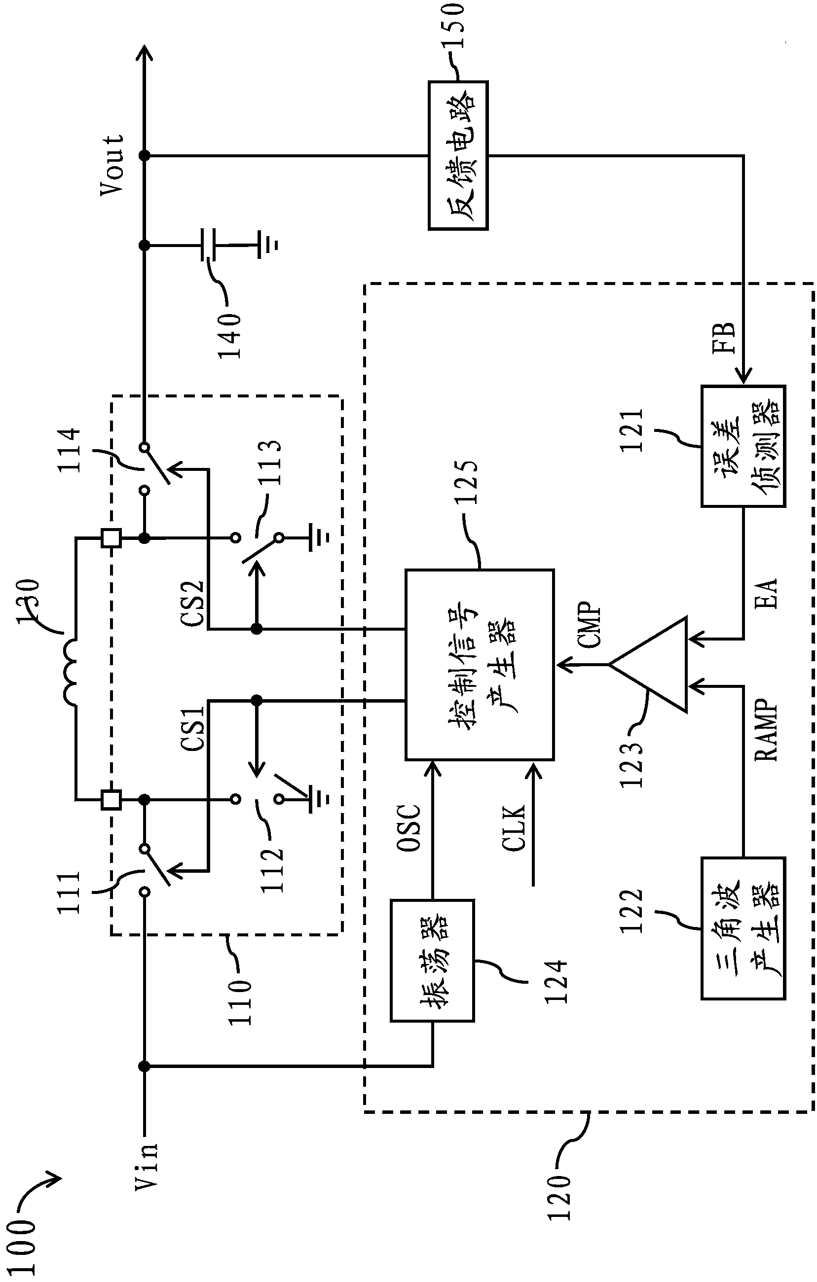
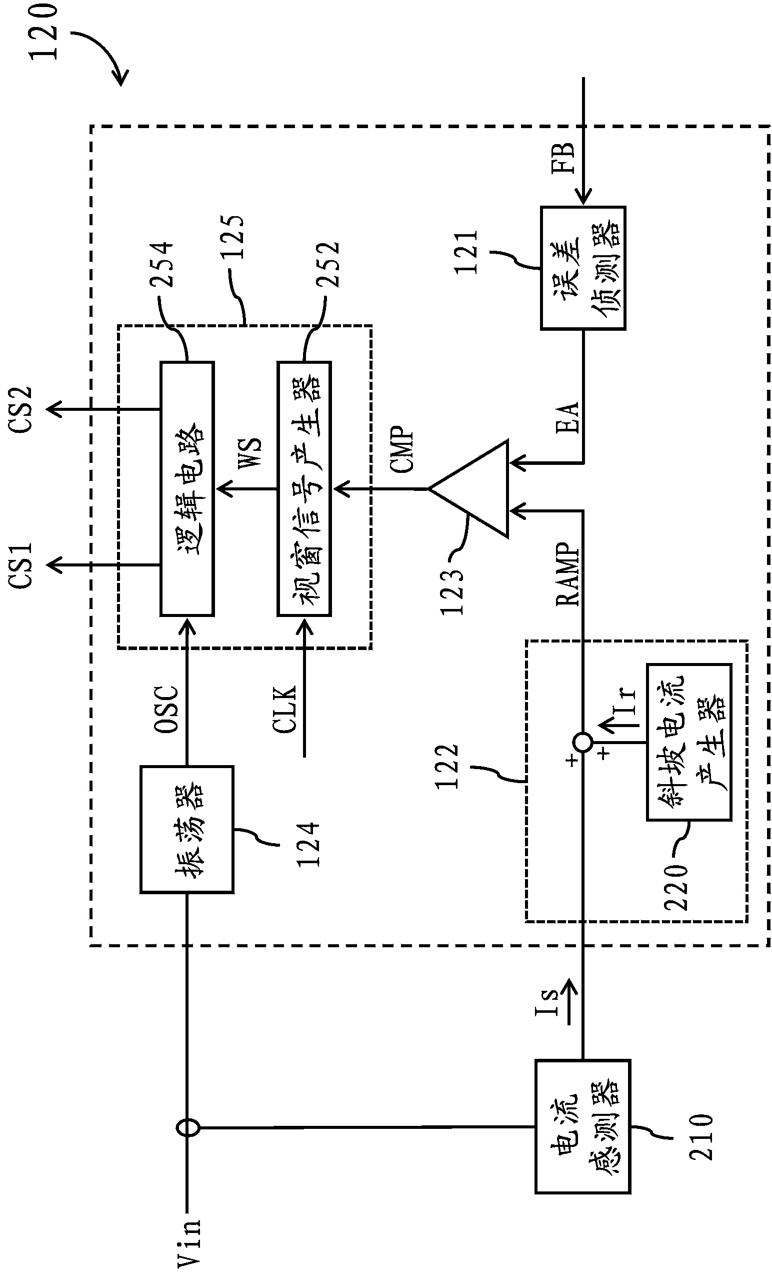
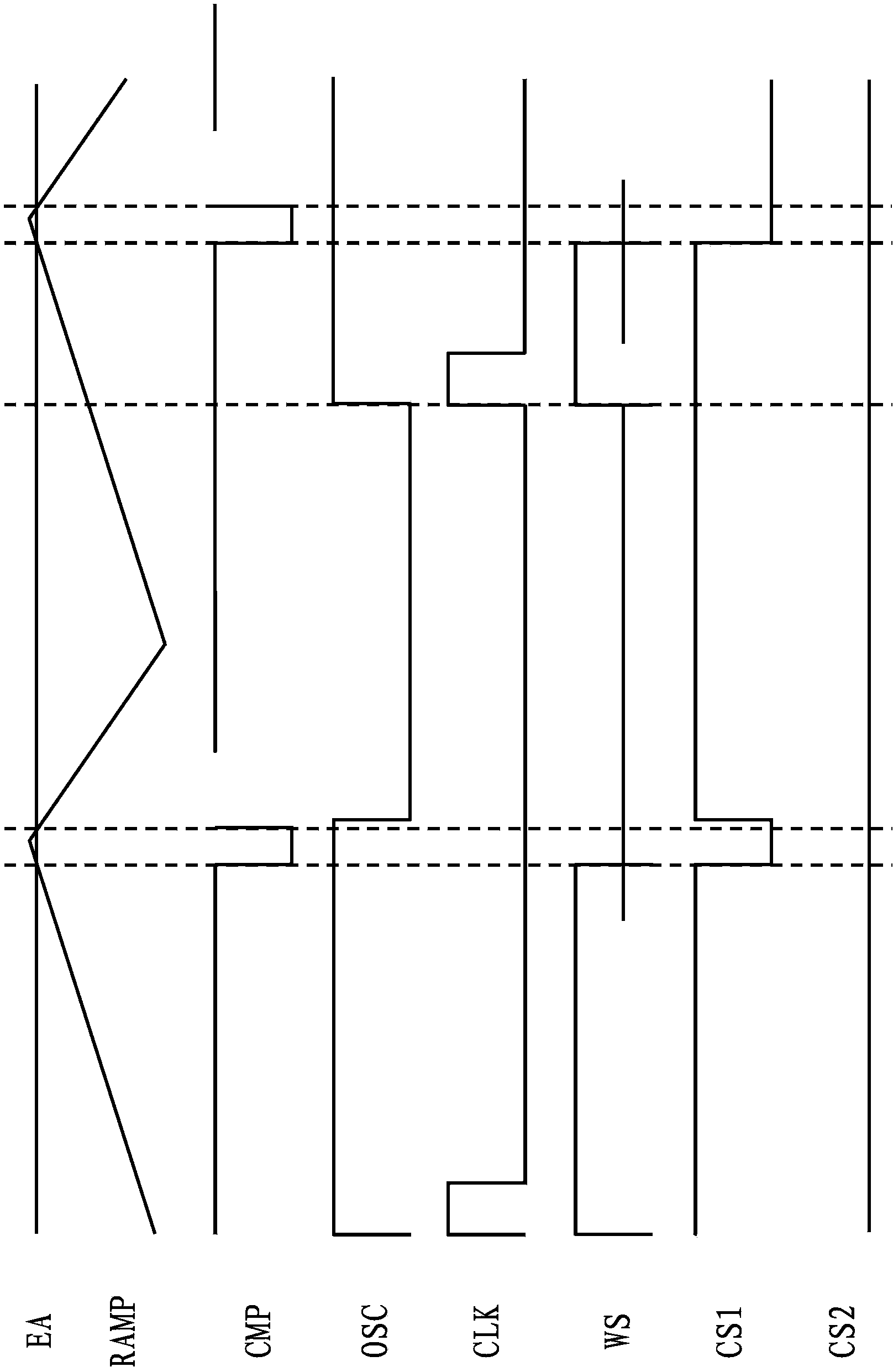
The invention discloses a control circuit used for controlling a switching type voltage stabilizer in a buck-boost converter. The switching type voltage stabilizer comprises a first switch, a second switch, a third switch and a fourth switch. The control circuit comprises an error detector, a triangular wave generator, a comparator, an oscillator and a control signal generator. The error detector is used for generating error signals corresponding to output voltage of the switching type voltage stabilizer. The triangular wave generator is used for generating triangular wave signals. The comparator is used for comparing the error signals with the triangular wave signals to generate comparison signals. The oscillator is used for generating oscillation signals. The control signal generator is used for controlling operation of the first switch, the second switch, the third switch and the fourth switch according to the comparison signals, the oscillation signals and time-impulse signals and used for enabling the switching type voltage stabilizer to be switched between a boosting mold and a voltage reduction mode and not to be operated in a buck-boost mode. The control circuit can prevent the switching type voltage stabilizer from entering the buck-boost mode, therefore, at most two switches of the switching type voltage stabilizer can be switched at the same time, and switching loss of the buck-boost converter can be effectively reduced.

Description

technical field [0001] The invention relates to the technology of the buck-boost converter, especially a control circuit and a related switching voltage regulator which can reduce the switching loss of the buck-boost converter. Background technique [0002] In a general buck-boost converter, a switching regulator is used in boost mode, buck mode, and buck-boost mode. mode) among the three alternate operation, in order to convert the input voltage into the required output voltage. [0003] Existing switching regulators contain four power switches. When the switching regulator operates in boost mode, only the two power switches in the switching regulator are turned on in turn. When the switching regulator operates in the step-down mode, the other two power switches are turned on in turn. [0004] When the input voltage is close to the output voltage, the existing switching regulator will operate in buck-boost mode. In the buck-boost mode, the four power switches in the swi...

Claims


Application Information

Patent Timeline
Patent Type & Authority Applications(China)
IPC IPC(8): H02M3/00
Inventor 吕建平
Owner RICHTEK TECH
Why Eureka
Eureka Blog
Learn More