Power storage unit and electronic device including the same

Inactive Publication Date: 2015-05-21
SEMICON ENERGY LAB CO LTD
View PDF3 Cites 28 Cited by
  • Summary
  • Abstract
  • Description
  • Claims
  • Application Information

AI Technical Summary

Benefits of technology

[0012]One embodiment of the present invention can provide a novel power storage unit, a novel manufacturing method thereof, or the like. For example, one embodiment of the present invention can provide a power storage unit in which a defect is unlikely to occur, a power storage unit which is unlikely to deteriorate, or a power storage unit having high reliability.
[0013]Note that the

Problems solved by technology

Furthermore, when a whisker grows abnormally and reaches the positive electrode, the positive electrode and the negative electrode are short-circuited.
For example, when the separator is displaced from the electrode plate, a short c

Method used


Image

  • Power storage unit and electronic device including the same
  • Power storage unit and electronic device including the same
  • Power storage unit and electronic device including the same

Examples


Example

Embodiment 1

[0050]In this embodiment, structural examples of a power storage unit, an example of a manufacturing method thereof, and the like are described.

[0051]>

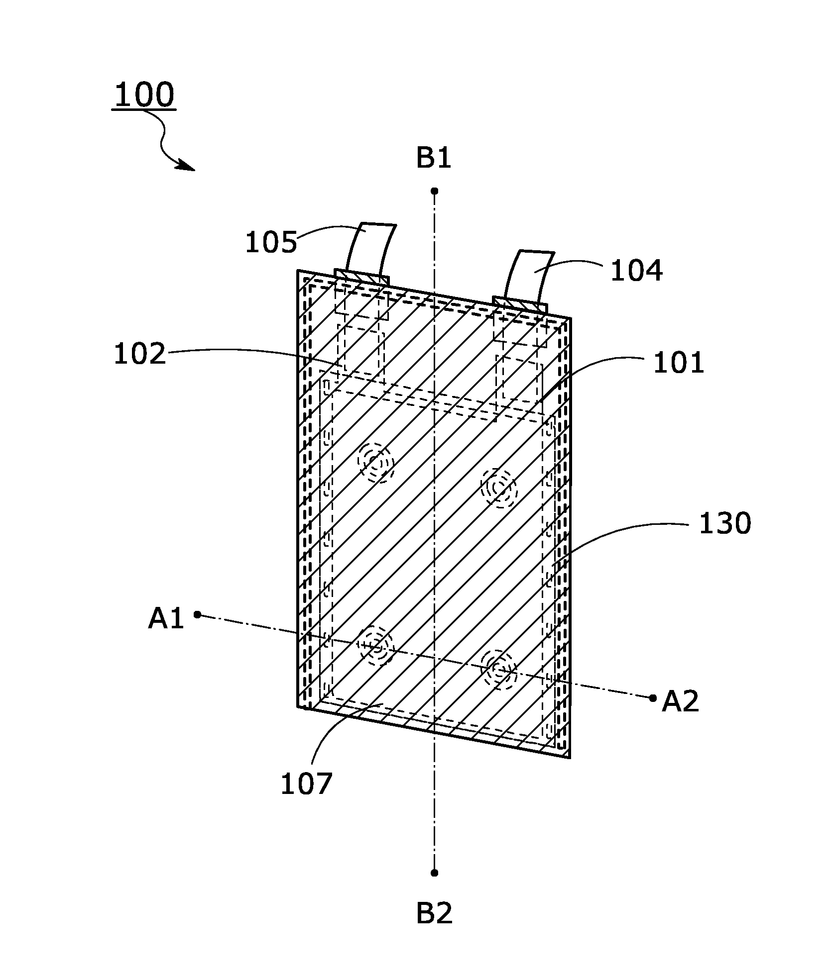
[0052]FIG. 1 is an external view showing a structural example of a power storage unit.

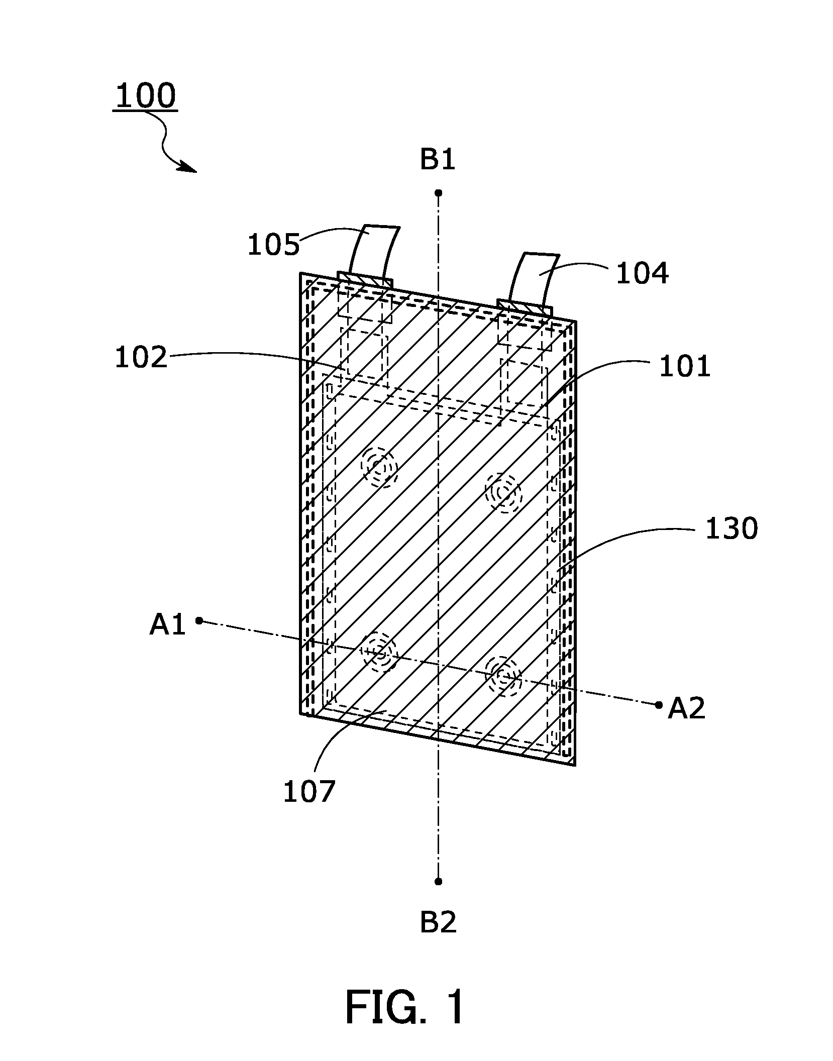
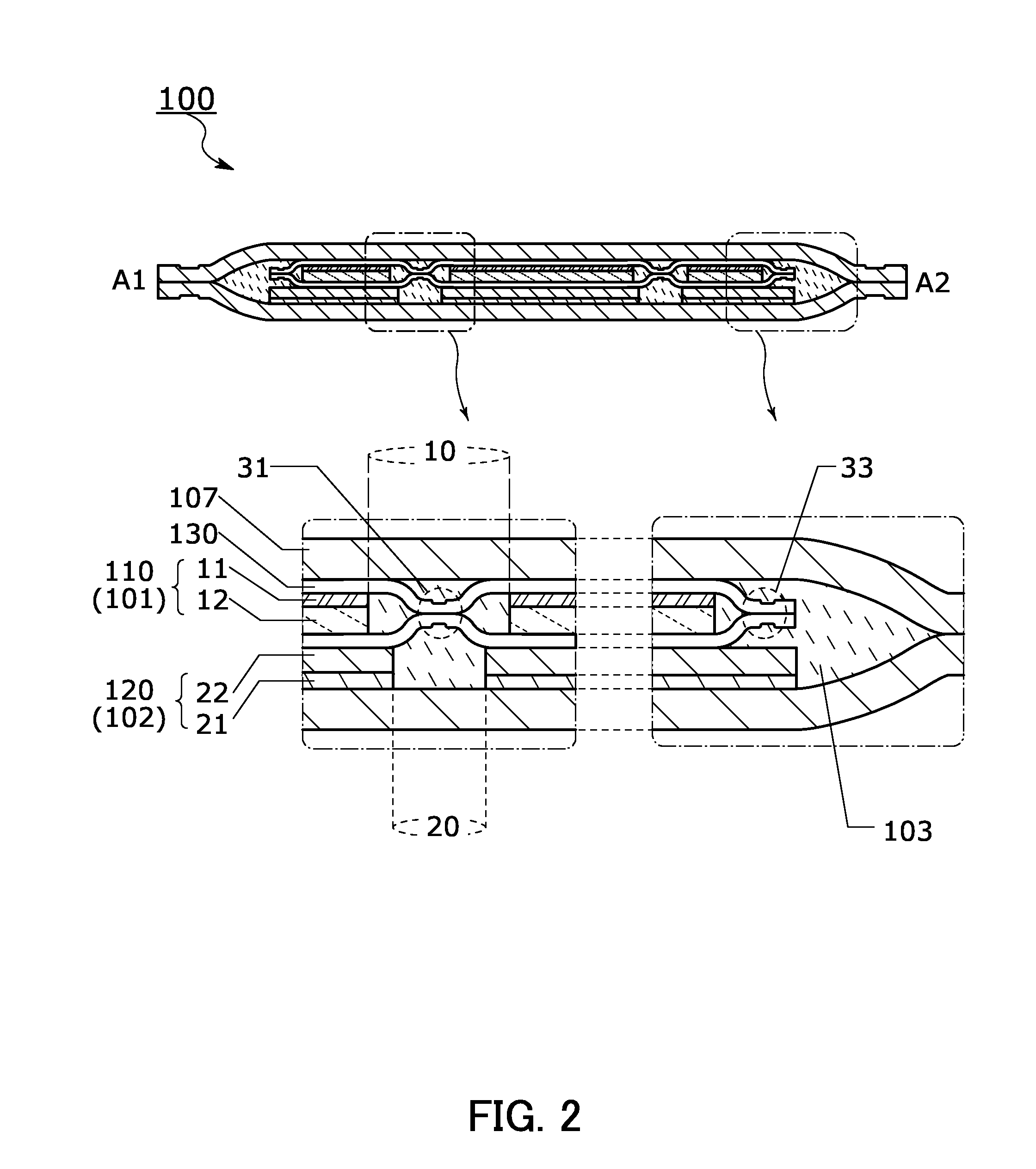
[0053]A cross-sectional view along the section line A1-A2 of FIG. 1 is shown in FIG. 2, and a cross-sectional view along the section line B1-B2 of FIG. 1 is shown in FIG. 3. Partially enlarged views are also shown in FIGS. 2 and 3. FIGS. 4A to 4E show structural examples of electrode plates. FIGS. 5A to 5D show a structural example of an envelope body and a manufacturing example thereof.

[0054]As illustrated in FIG. 1, a power storage unit 100 includes a positive electrode 101, a negative electrode 102, a positive electrode lead 104, a negative electrode lead 105, and an exterior body 107. The positive electrode 101, the negative electrode 102, and an electrolyte solution 103 are sealed in the exterior body 107. The positive electrode 101 ...

Example

[0136]In Structural example 1, an example in which one electrode plate is included in each of the positive electrode 101 and the negative electrode 102 is described. In a structural example below, an example in which two or more electrode plates are included in each of the positive electrode 101 and the negative electrode 102 is described.

[0137]FIG. 10 is an external view showing a structural example of a power storage unit. A cross-sectional view along the section line A3-A4 in FIG. 10 is shown in FIG. 11. A cross-sectional view along the section line B3-B4 in FIG. 10 is shown in FIG. 12. Partially enlarged views are also shown in FIGS. 11 and 12. FIGS. 13A to 13D show structural examples of electrode plates.

[0138]Like the power storage unit 100, a power storage unit 200 includes the positive electrode 101, the negative electrode 102, the positive electrode lead 104, the negative electrode lead 105, and the exterior body 107. The positive electrode 101, the negative electrode 102, ...

Example

Embodiment 2

[0170]The power storage unit of one embodiment of the present invention can be used as a power supply of various electronic devices which are driven by electric power. FIGS. 25A to 25G, FIGS. 26A to 26C, FIG. 27, and FIGS. 28A and 28B illustrate specific examples of the electronic devices using a power storage unit of one embodiment of the present invention.

[0171]Specific examples of the electronic devices using the power storage unit of one embodiment of the present invention are as follows: display devices of televisions, monitors, and the like, lighting devices, desktop and laptop personal computers, word processors, image reproduction devices which reproduce still images and moving images stored in recording media such as digital versatile discs (DVDs), portable CD players, radios, tape recorders, headphone stereos, stereos, table clocks, wall clocks, cordless phone handsets, transceivers, mobile phones, car phones, portable game machines, tablet terminals, large gam...


PUM


Abstract

A short-circuit between a positive electrode and a negative electrode due to a deposit on an electrode plate is prevented in a power storage unit such as a lithium-ion secondary battery. An electrode plate is covered by a folded insulating sheet. Bonding is performed on facing edges of the sheet which overlap with each other in a portion outer than the electrode plate. One or more openings are formed in the electrode plate, and the facing edges of the folded sheet are bonded to each other also in the opening. Such a bonding portion enables the sheet to be in closer contact with the electrode plate and prevents the displacement between the sheet and the electrode plate. When the electrode plate is deformed or vibrated, the sheet can be rubbed against a surface of the electrode plate, thereby removing a deposit from the surface of the electrode plate.

Description

TECHNICAL FIELD[0001]The present invention relates to an object, a method, or a manufacturing method. The present invention relates to a process, a machine, manufacture, or a composition of matter. For example, one embodiment of the present invention relates to a power storage unit, a manufacturing method thereof, or the like. For example, one embodiment of the present invention relates to a power storage device, a semiconductor device, a display device, a light-emitting device, a memory device, a driving method thereof, a manufacturing method thereof, or the like.BACKGROUND ART[0002]A variety of power storage units such as lithium-ion secondary batteries, lithium-ion capacitors, and air batteries have been actively developed. In particular, with the development of the semiconductor industry, demand for lithium-ion secondary batteries with high output and high energy density (see Patent Document 1, for example) has rapidly grown for electronic devices, for example, portable informat...

Claims


Application Information

Patent Timeline
IPC IPC(8): H01M10/04H01M2/18H01M50/466H01M50/55H01M50/557
CPCH01M2/18H01M10/0459H01M10/0585Y02E60/10H01M50/557Y02P70/50H01M50/55H01M50/466Y02E60/13H01M50/463
Inventor YAMAZAKI, SHUNPEITAKAHASHI, MINORUTAJIMA, RYOTA
Owner SEMICON ENERGY LAB CO LTD
Why Eureka
Try Eureka