Check patentability & draft patents in minutes with Patsnap Eureka AI!

Thin connector

a technology of connectors and connectors, applied in the direction of electrical equipment, electrical discharge tubes, coupling device connections, etc., can solve the problems of limited receptacle contact size reduction, difficult to narrow the arrangement pitch of receptacle contacts, etc., and achieve the effect of narrowing the arrangement pitch

Active Publication Date: 2015-06-11
JAPAN AVIATION ELECTRONICS IND LTD
View PDF6 Cites 2 Cited by
  • Summary
  • Abstract
  • Description
  • Claims
  • Application Information

AI Technical Summary

Benefits of technology

The present invention aims to provide a thin connector that can easily narrow the arrangement pitch. This solves the problem that conventional connectors have with their large arrangement pitch, making them difficult to use in tight spaces.

Problems solved by technology

Accordingly, reduction in size of the receptacle contact 5 has been limited, and it has been difficult to narrow the arrangement pitch of the receptacle contacts 5.

Method used


Image

  • Thin connector
  • Thin connector
  • Thin connector

Examples


Embodiment Construction

[0035]Embodiments of the present invention will be described below based on the appended drawings.

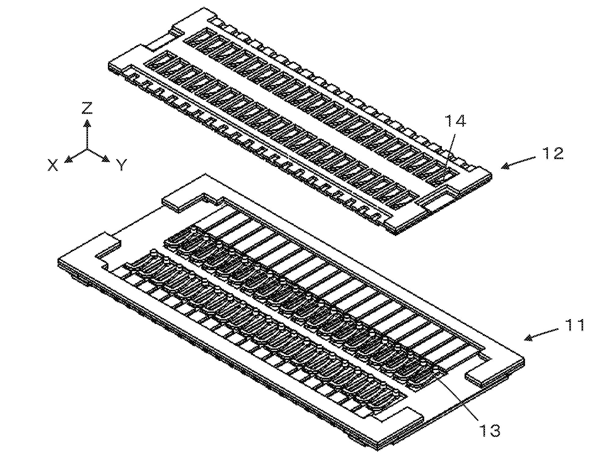
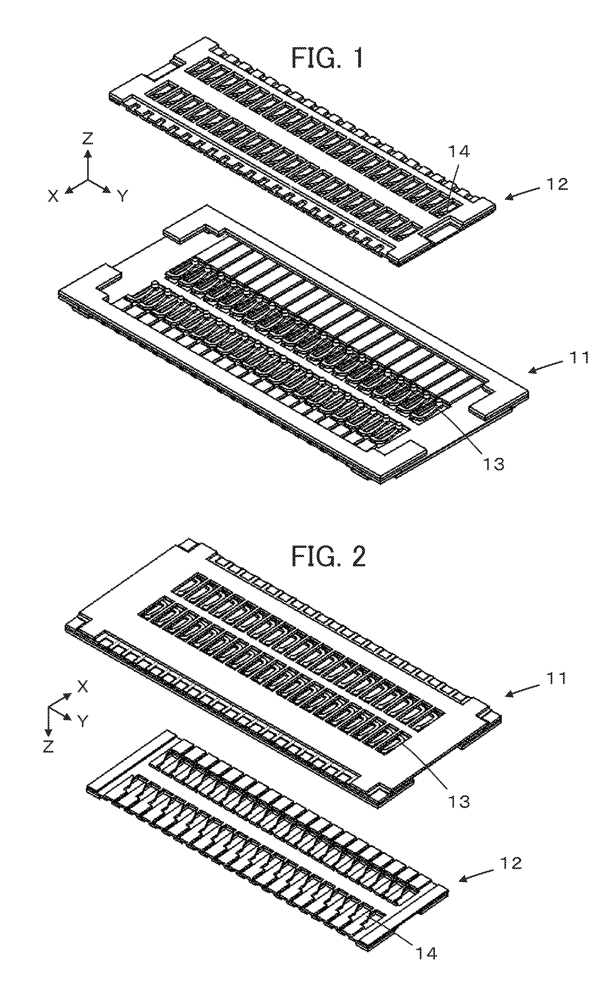
[0036]FIGS. 1 and 2 illustrate a configuration of a thin connector according to an embodiment of the present invention. The thin connector comprises a flat plate receptacle (first connector) 11 and a flat plate plug (second connector) 12, and the receptacle 11 and the plug 12 are superimposed on each other to be fitted together. FIGS. 1 and 2 illustrate the receptacle 11 and the plug 12 that are placed in parallel and apart from each other, and FIG. 1 is a view when viewed obliquely from above while FIG. 2 is a view when viewed obliquely from below.

[0037]The receptacle 11 includes a plurality of receptacle contacts (first contacts) 13 arranged in two arrays, while the plug 12 includes a plurality of plug contacts (second contacts) 14 arranged in two arrays.

[0038]In this regard, a plane along which the flat plate receptacle 11 and the flat plate plug 12 extend is assumed to be an XY plan...


PUM


Abstract

A thin connector comprises a first connector having a flat plate shape and a second connector having a flat plate shape superimposed on and fitted with each other, the first connector including first contacts arrayed in a direction, each first contact having a spring portion composed of a first metal member in a flat plate shape, a projection portion formed on the spring portion so as to protrude in a perpendicular direction to the plane of the first metal member, and a first contact portion formed on a side surface of the projection portion, the second connector including second contacts arrayed in a same direction as the direction in which the first contacts are arrayed, each second contact being composed of a second metal member in a flat plate shape and having a second contact portion formed on a side surface of the second metal member.

Description

BACKGROUND OF THE INVENTION[0001]The present invention relates to a thin connector, in particular, to a substrate-to-substrate connector comprising a first connector having a flat plate shape and a second connector having a flat plate shape superimposed on and fitted with each other in a fitting plane.[0002]As a connector of this type, for example, JP 2012-226977 A discloses a connector as illustrated in FIG. 18. The connector comprises a receptacle 2 mounted on a first substrate 1 and a plug 4 (not shown) mounted on a second substrate 3. In the receptacle 2, a plurality of receptacle contacts 5 having spring characteristics are formed to be arrayed as illustrated in FIG. 19, and in the plug 4, protruding plug contacts 6 are formed to be arrayed as illustrated in FIG. 20.[0003]Each of the receptacle contacts 5 has a main arm portion 5a curved so as to form inside thereof an opening portion S, an auxiliary arm portion 5b provided so as to face the main arm portion 5a, and a projectio...

Claims


Application Information

Patent Timeline
Patent Type & Authority Applications(United States)
IPC IPC(8): H01R12/71
CPCH01R12/716H01R12/714H01R12/73
Inventor KOMOTO, TETSUYA
Owner JAPAN AVIATION ELECTRONICS IND LTD
Features
  • R&D
  • Intellectual Property
  • Life Sciences
  • Materials
  • Tech Scout
  • Unparalleled Data Quality
  • Higher Quality Content
  • 60% Fewer Hallucinations
Learn More