Wireless communication apparatus and transmission power control method

Active Publication Date: 2015-06-11
PANASONIC CORP
View PDF6 Cites 6 Cited by
  • Summary
  • Abstract
  • Description
  • Claims
  • Application Information

AI Technical Summary

Benefits of technology

This patent is about making sure that the signal intensity of a wireless antenna is always strong, even if the antenna's performance changes. This helps to maintain constant communication quality.

Problems solved by technology

Furthermore, since variation in antenna gain is apt to occur in millimeter wave band wireless communication, there has been a problem that the EIRP (Effective Isotropic Radiated Power) of an antenna in a wireless communication apparatus is apt to vary.

Method used


Image

  • Wireless communication apparatus and transmission  power control method
  • Wireless communication apparatus and transmission  power control method
  • Wireless communication apparatus and transmission  power control method

Examples


Embodiment Construction

Background to Contents of Embodiments of Disclosure

[0018]Before the description of a wireless communication apparatus and a transmission power control method according to an embodiment of the present disclosure, first, circumstances leading to the contents of this embodiment will be described referring to FIGS. 6 and 7. FIG. 6 is a block diagram showing part of the conventional wireless communication apparatus (refer to Patent Document 1). FIG. 7 is a graph showing the relationship between a used channel and the passage loss of a transmission / reception branching filter in the conventional wireless communication apparatus (refer to Patent Document 1).

[0019]In the wireless communication apparatus shown in FIG. 6, a transmission / reception branching filter 3 is connected via a directional coupler 2 to the output terminal of a power amplifier 1 for amplifying the electric power of a transmission signal modulated in a transmission section (not shown), and an antenna 4 is connected to one ...


PUM


Abstract

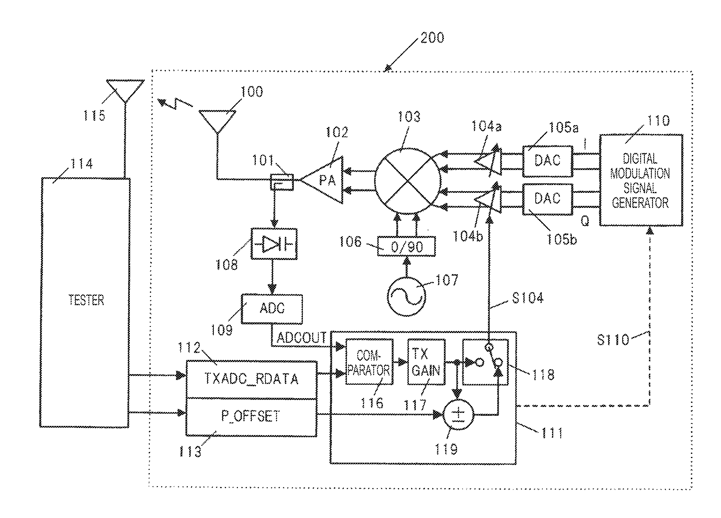
A variable gain amplifier amplifies a baseband signal. A quadrature modulator quadrature-modulates the amplified baseband signal to generate a high-frequency signal. A power amplifier amplifies the generated high-frequency signal. An antenna transmits the amplified high-frequency signal. A detector detects the amplified high-frequency signal. A first nonvolatile memory stores the desired transmission power of the high-frequency signal to be transmitted from the antenna. A controller adjusts the gain of the variable gain amplifier depending on the output of the detector and the transmission power stored in the first nonvolatile memory.

Description

TECHNICAL FIELD[0001]The present disclosure relates to a wireless communication apparatus and a transmission power control method for controlling the transmission power of a high-frequency signal.[0002]In recent years, as the micro-fabrication technology in CMOS (Complementary Metal Oxide Semiconductor) processes advances, integrated circuits for millimeter wave wireless communication using, for example, a 60 GHz band, have been put into practical use. The operating frequency of such an integrated circuit for millimeter wave band wireless communication is higher than the operating frequency of an integrated circuit for microwave band wireless communication, thereby becoming the high cutoff frequency ft in a CMOS process; in other words, the current gain becomes one time; hence, the difference between the frequency at which the integrated circuit is difficult to be used as an amplifying element and the operating frequency thereof decreases, whereby the two frequencies are close to ea...

Claims


Application Information

Patent Timeline
IPC IPC(8): H04L27/36H04L27/34
CPCH04L27/3405H04L27/362H03G3/3042
InventorSAITO, NORIAKIMIYANAGA, KENJITSUKIZAWA, TAKAYUKI
OwnerPANASONIC CORP