This helps you quickly interpret patents by identifying the three key elements:
Problems solved by technology
Method used
Benefits of technology
Benefits of technology
The patent text is about a way to manage and control the temperature, humidity, pressure, wind, and cleanliness inside a building to make people comfortable. The goal is to provide a comfortable environment while reducing power consumption. The text identifies the problem to be solved as how to manage these factors in a balanced way.
Problems solved by technology
However, as traditional controlling method of air conditioning systems is predetermined in fixed values, therefore, it can not be applied to suit the measure to local conditions in different situations.
If the predetermined fixed values are not appropriately set up, not only the environment thermal comfort inside a building is reduced, but also power consumption of an air conditioning system is increased without considering environment factors in many ways.
Therefore, it would be problems to be solved that are how to take indoor environment factors such as temperature, humidity into consideration, and to maintain environment thermal comfort for indoor personnel and reduce power consumption in the same time.
Method used
Image
Click on the blue label to locate the original text in one second.
Reading with bidirectional positioning of images and text.
Examples
first embodiment
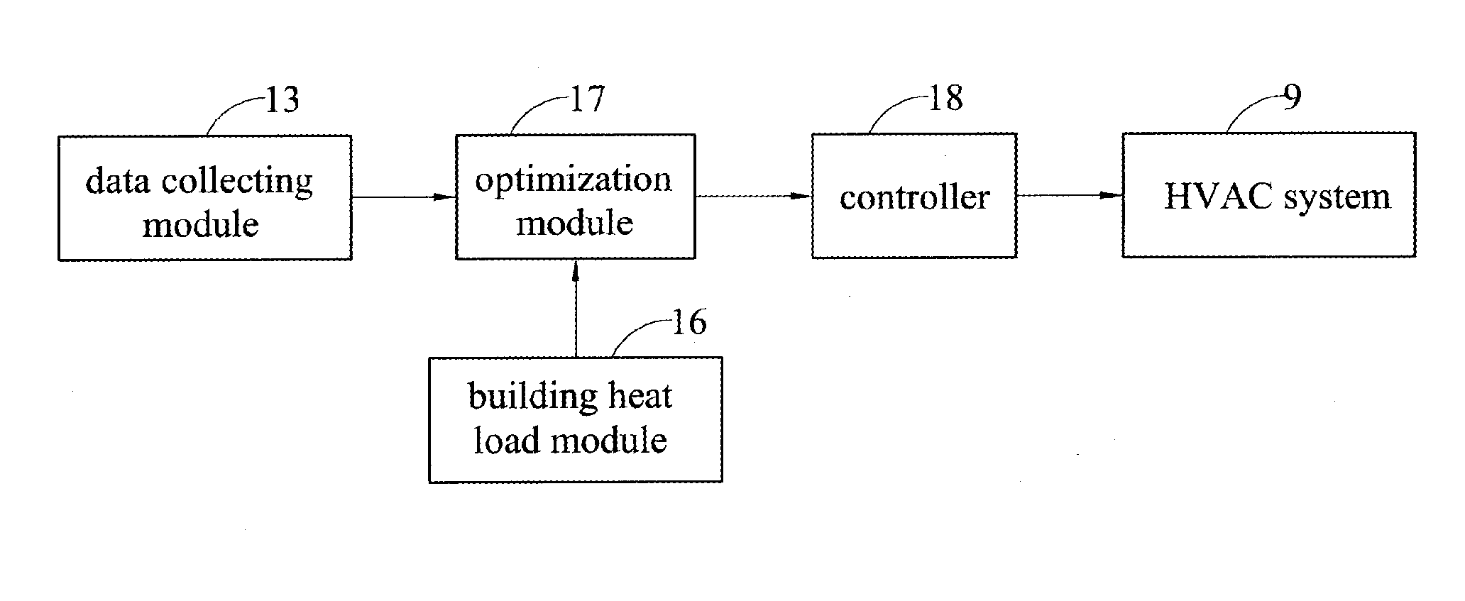
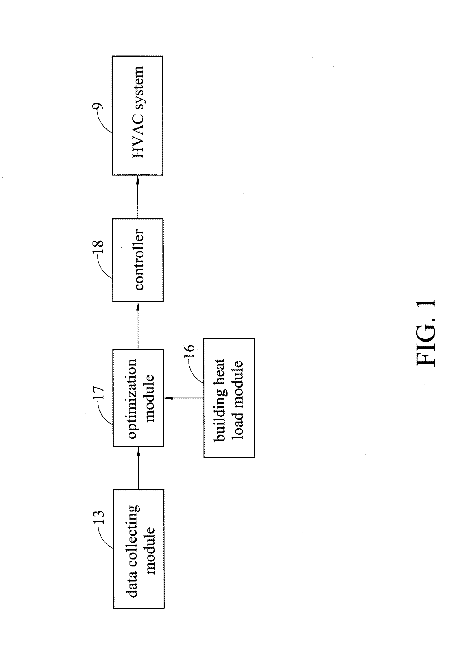
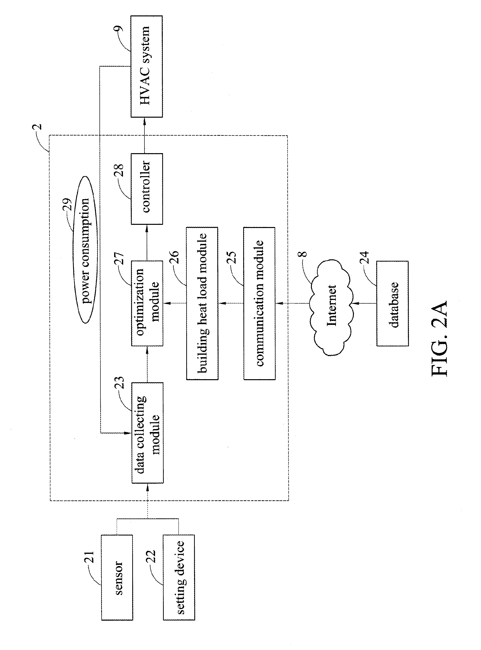
[0028]FIG. 2A illustrates a controlling device for an HVAC system 9 in accordance with the present disclosure. The controlling device comprises a sensor 21, a setting device 22, a data collecting module 23, a database 24, a communication module 25, a building heat load module 26, an optimization module 27, and a controller 28.
[0029]The data collecting module 13 is used for collecting field information data obtained by the sensor 21 which senses indoor environment of a building. The setting device 22 sets predetermined data of the indoor environment of the building, and power consumption 29 of the HVAC system 9. The field information data may be gases concentration, for example, CO2 concentration, and / or room temperature, and / or room humidity, and the predetermined data is the predetermined indoor temperature.
[0030]The database 24 is used for storing building envelope data, for example, building materials used in indoor space, such as walls, ceilings, floors, window and door material...
second embodiment
[0036]FIG. 2B illustrates a controlling device for an HVAC system 9 in accordance with the present disclosure. The building heat load module 26 and the database 24 are simultaneously located in the cloud environment, and transmit data through the Internet 8 to a control equipment 2′, which integrates the data collecting module 23, the communication module 25, the optimization module 27, and a controller 28.
third embodiment
[0037]FIG. 2C illustrates a controlling device for an HVAC system 9 in accordance with the present disclosure. The building heat load module 26, the optimization module 27, and the database 24 are located in the cloud environment, and transmit data through the Internet 8 to a control equipment 2″, which integrates the data collecting module 23, the communication module 25, and the controller 28.
[0038]Based on three different embodiment types as shown in FIGS. 2A, 2B, and 2C, the user can apply different equipments according to different indoor space factors and his / her demand, and, furthermore, the different equipments can be modified as to fit different commercial types to promote effect of economic benefits.
[0039]FIG. 3 illustrates a flow chart of a controlling method for an HVAC system according to the present disclosure. Firstly, in step S31, the building envelope data are collected to establish the building heat load model, and the field information data and setup data are coll...
CROSS-REFERENCE TO RELATED APPLICATIONS[0001]This application claims priority to Taiwanese Application Serial No. 102145813, filed on Dec. 12, 2013. The entirety of the above-mentioned patent application is hereby incorporated by reference herein and made a part of this specification.BACKGROUND[0002]1. Technical Field[0003]The present disclosure relates to controlling devices and methods, and, in particular, to a controlling device and method for an HVACsystem.[0004]2. Description of Related Art[0005]The air conditioning system is used for controlling and maintaining temperature, humidity, pressure, wind, and cleanness inside a building in a predetermined range to make personnel live comfortably inside an environment of the building. A heating, ventilation and air conditioning (HVAC) system is one of the air conditioning systems as know by person having ordinary skills in the art.[0006]However, as traditional controlling method of air conditioning systems is predetermined in fixed ...
Claims
Application Information
Patent Timeline
Application Date:The date an application was filed.
Publication Date:The date a patent or application was officially published.
First Publication Date:The earliest publication date of a patent with the same application number.
Issue Date:Publication date of the patent grant document.
PCT Entry Date:The Entry date of PCT National Phase.
Estimated Expiry Date:The statutory expiry date of a patent right according to the Patent Law, and it is the longest term of protection that the patent right can achieve without the termination of the patent right due to other reasons(Term extension factor has been taken into account ).
Invalid Date:Actual expiry date is based on effective date or publication date of legal transaction data of invalid patent.

