Controlling device and method for HVAC system

a control device and hvac technology, applied in lighting and heating apparatus, heating types, instruments, etc., can solve the problems of not being able to adapt to local conditions in different situations, reducing the thermal comfort of the environment inside the building, and increasing the power consumption of the air conditioning system without considering many environmental factors. the effect of optimal setup data, optimal computation and optimal setup data

Active Publication Date: 2018-02-13
IND TECH RES INST
View PDF40 Cites 4 Cited by
  • Summary
  • Abstract
  • Description
  • Claims
  • Application Information

AI Technical Summary

Benefits of technology

[0005]The air conditioning system is used for controlling and maintaining temperature, humidity, pressure, wind, and cleanness inside a building in a predetermined range to make personnel live comfortably inside an environment of the building. A heating, ventilation and air conditioning (HVAC) system is one of the air conditioning systems as know by person having ordinary skills in the art.
[0008]Therefore, it would be problems to be solved that are how to take indoor environment factors such as temperature, humidity into consideration, and to maintain environment thermal comfort for indoor personnel and reduce power consumption in the same time.

Problems solved by technology

However, as traditional controlling method of air conditioning systems is predetermined in fixed values, therefore, it can not be applied to suit the measure to local conditions in different situations.
If the predetermined fixed values are not appropriately set up, not only the environment thermal comfort inside a building is reduced, but also power consumption of an air conditioning system is increased without considering environment factors in many ways.
Therefore, it would be problems to be solved that are how to take indoor environment factors such as temperature, humidity into consideration, and to maintain environment thermal comfort for indoor personnel and reduce power consumption in the same time.

Method used


Image

  • Controlling device and method for HVAC system
  • Controlling device and method for HVAC system
  • Controlling device and method for HVAC system

Examples


first embodiment

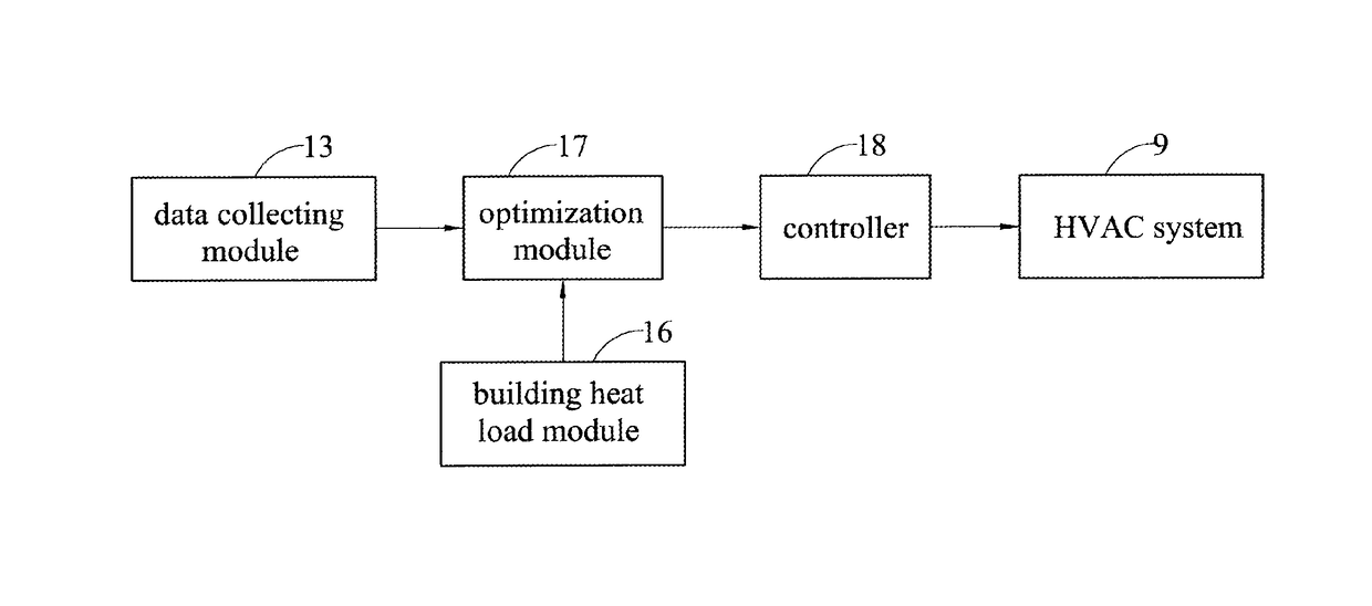
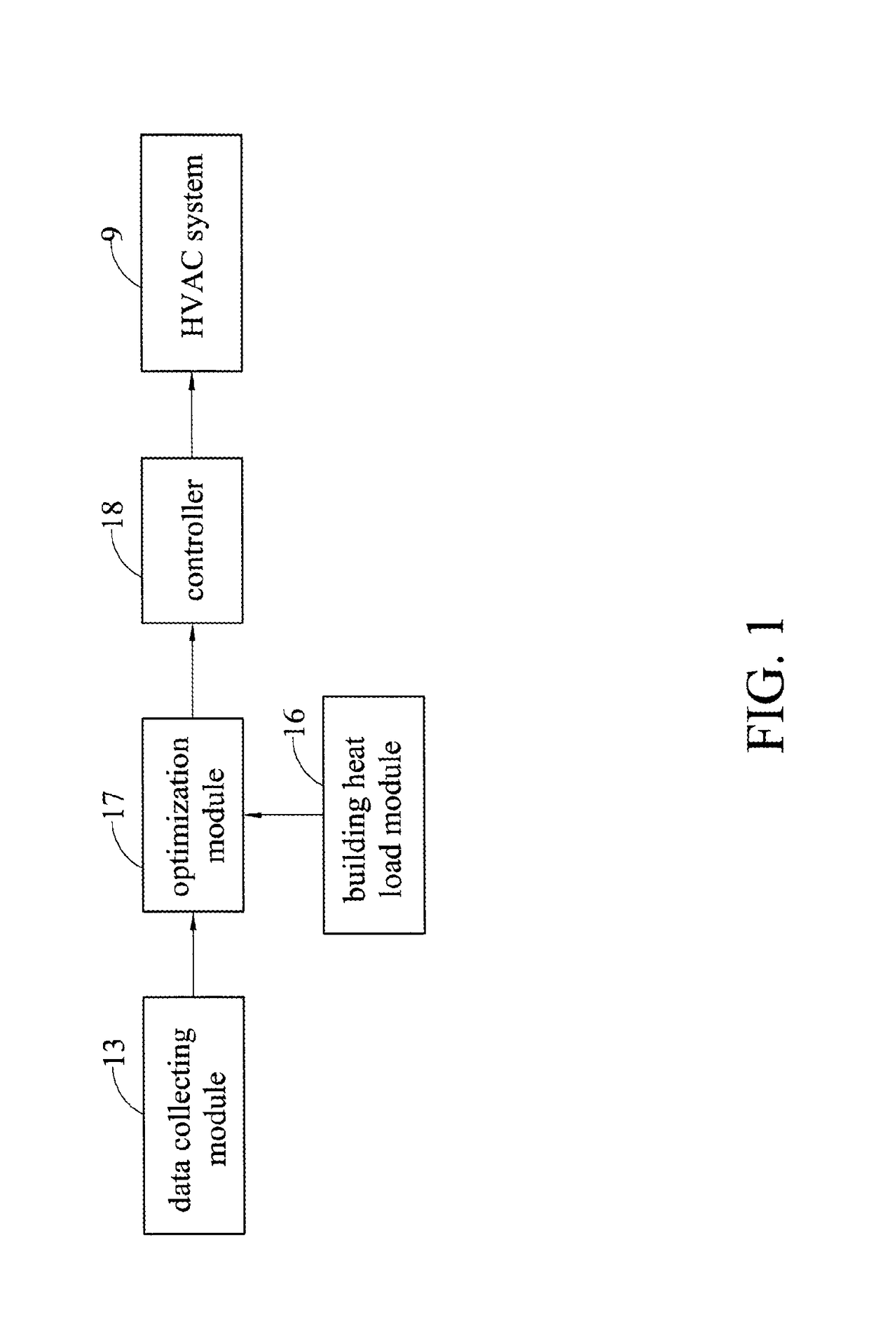
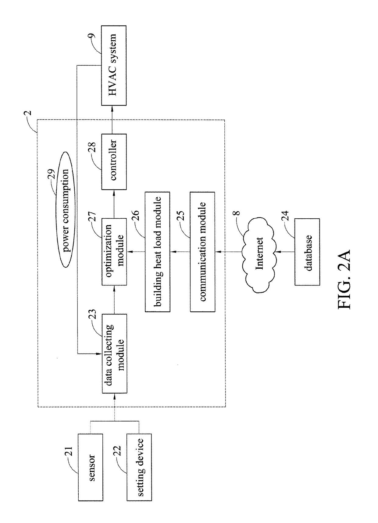
[0030]FIG. 2A illustrates a controlling device for an HVAC system 9 in accordance with the present disclosure. The controlling device comprises a sensor 21, a setting device 22, a data collecting module 23, a database 24, a communication module 25, a building heat load module 26, an optimization module 27, and a controller 28.

[0031]The data collecting module 13 is used for collecting field information data obtained by the sensor 21 which senses indoor environment of a building. The setting device 22 sets predetermined data of the indoor environment of the building, and power consumption 29 of the HVAC system 9. The field information data may be gases concentration, for example, CO2 concentration, and / or room temperature, and / or room humidity, and the predetermined data is the predetermined indoor temperature.

[0032]The database 24 is used for storing building envelope data, for example, building materials used in indoor space, such as walls, ceilings, floors, window and door material...

second embodiment

[0040]FIG. 2B illustrates a controlling device for an HVAC system 9 in accordance with the present disclosure. The building heat load module 26 and the database 24 are simultaneously located in the cloud environment, and transmit data through the Internet 8 to a control equipment 2′, which integrates the data collecting module 23, the communication module 25, the optimization module 27, and a controller 28.

third embodiment

[0041]FIG. 2C illustrates a controlling device for an HVAC system 9 in accordance with the present disclosure. The building heat load module 26, the optimization module 27, and the database 24 are located in the cloud environment, and transmit data through the Internet 8 to a control equipment 2″, which integrates the data collecting module 23, the communication module 25, and the controller 28.

[0042]Based on three different embodiment types as shown in FIGS. 2A, 2B, and 2C, the user can apply different equipments according to different indoor space factors and his / her demand, and, furthermore, the different equipments can be modified as to fit different commercial types to promote effect of economic benefits.

[0043]FIG. 3 illustrates a flow chart of a controlling method for an HVAC system according to the present disclosure. Firstly, in step S31, the building envelope data are collected to establish the building heat load model, and the field information data and setup data are coll...


PUM


Abstract

The present disclosure discloses a controlling device and method for a Heating Ventilation and Air Conditioning system. The controlling device includes a building heat load module, a data collecting module, an optimization module, and a controller. A building heat load model is established according to building envelope data. Field information data and setup data are collected. The building heat load model, the field information data, and the setup data are integrated to produce optimal setup data by optimal computation. According to the optimal setup data, the HVAC system proceeds to modulate room temperature, room humidity, or gas concentration to achieve functions of maintaining indoor thermal comfort and energy conservation.

Description

CROSS-REFERENCE TO RELATED APPLICATIONS[0001]This application claims priority to Taiwanese Application Serial No. 102145813, filed on Dec. 12, 2013. The entirety of the above-mentioned patent application is hereby incorporated by reference herein and made a part of this specification.BACKGROUND[0002]1. Technical Field[0003]The present disclosure relates to controlling devices and methods, and, in particular, to a controlling device and method for an HVAC system.[0004]2. Description of Related Art[0005]The air conditioning system is used for controlling and maintaining temperature, humidity, pressure, wind, and cleanness inside a building in a predetermined range to make personnel live comfortably inside an environment of the building. A heating, ventilation and air conditioning (HVAC) system is one of the air conditioning systems as know by person having ordinary skills in the art.[0006]However, as traditional controlling method of air conditioning systems is predetermined in fixed ...

Claims


Application Information

Patent Timeline
Patent Type & Authority Patents(United States)
IPC IPC(8): G05D23/00G05D23/19F24F11/00
CPCG05D23/1917F24F11/61F24F11/62F24F11/63F24F11/46F24F11/30F24F11/56F24F11/58F24F11/64
Inventor WU, MIN-DERYANG, YAU-BINLIU, YANG-GUANGTSAI, MENG-YENLIN, MIN-JUTU, WEI-DA
Owner IND TECH RES INST
Why Eureka
Try Eureka