Display apparatus

a technology for display apparatuses and display cases, which is applied to electrical apparatus casings/cabinets/drawers, display/control units, identification means, etc., can solve the problems of reducing the view angle, generating noise, and consuming electrical power by fans, so as to improve visibility, reduce power consumption, and avoid frost damage.

Active Publication Date: 2015-11-12
PERMIUM ELECTRONICS CO LTD
View PDF4 Cites 5 Cited by
  • Summary
  • Abstract
  • Description
  • Claims
  • Application Information

AI Technical Summary

Benefits of technology

[0004]It is an object of the invention to provide a display apparatus which has at least one of the following advantages: the display apparatus does not require regular maintenance, has improved visibility under all weather conditions, does not have to be powered...

Problems solved by technology

The maintenance of an outdoor display apparatus is very costly.
The air space between the transparent member and the display panel causes poor visibility from light reflection and possible contamination by foreign particles and will reduced the view angle.
Further, the fans will consume electrical power and generate noise.
The apparatus will face internal moisture condensation if the ambient temperature is around zero degrees Celsius and even frost damage to the display panel glass layers especially if the a...

Method used


Image

  • Display apparatus
  • Display apparatus
  • Display apparatus

Examples


first embodiment

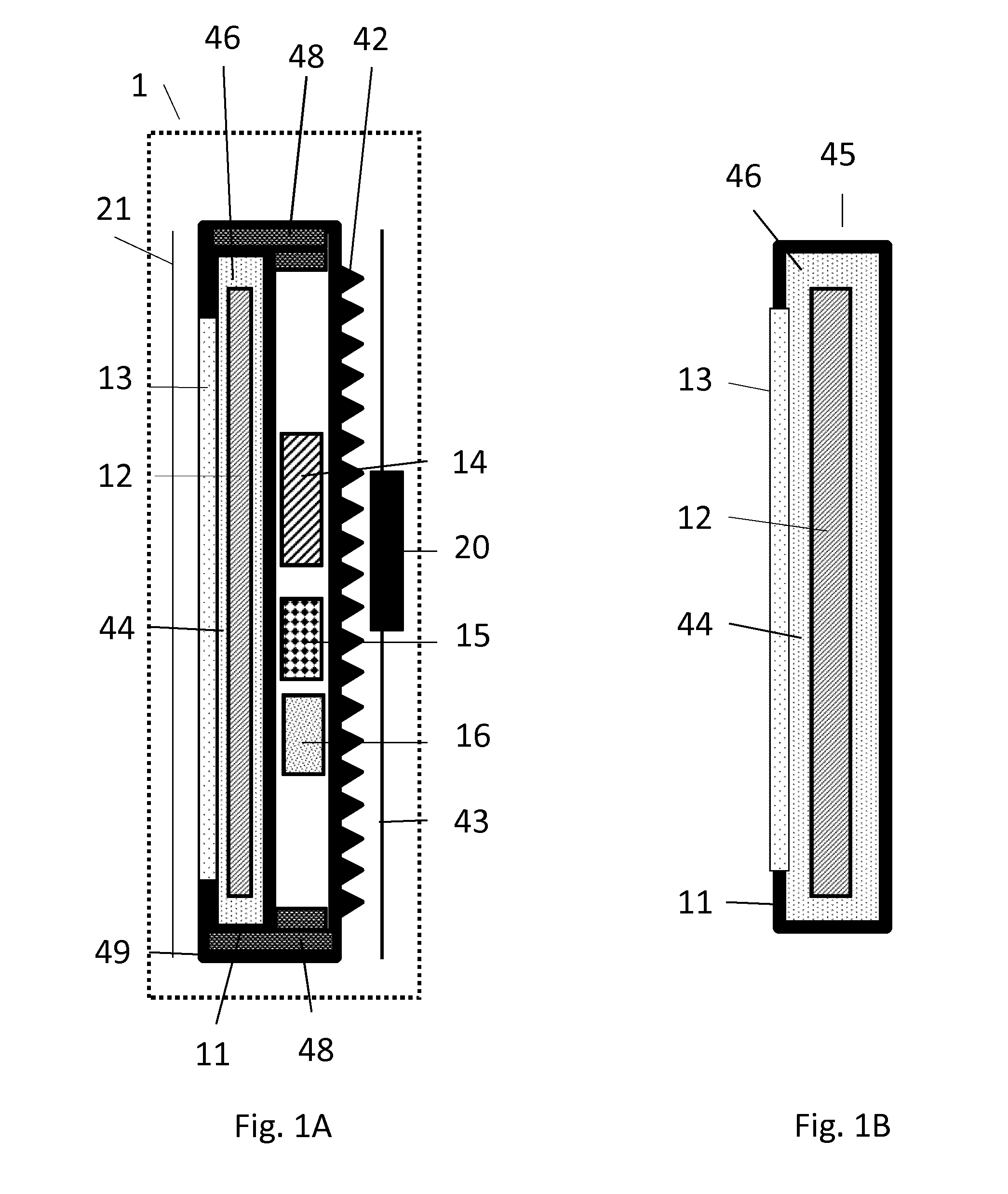
[0028]FIGS. 1A and 1B schematically show a first embodiment in accordance with the present invention. FIG. 1A shows a display apparatus 1 with a module 45. The display apparatus is of the type suitable for direct view of the pixels of the display panel and is not intended to cover projection systems which anyhow are considered too bulky in the context of the present invention. The term direct view display panel therefore indicates that a spectator can directly view the information on the display panel via the transparent window 13.

[0029]FIG. 1B shows the module 45 in isolation. The module 45 comprises the liquid tight encasing 11 with the transparent window 13. The liquid tight encasing is filed with a thermal conductive liquid 46. The direct view display panel 12 is arranged inside the liquid tight encasing 11 and is submerged in the thermal conductive liquid 46. It is not essential for the present invention that the thermal conductive liquid 46 is present at all sides of the direc...

second embodiment

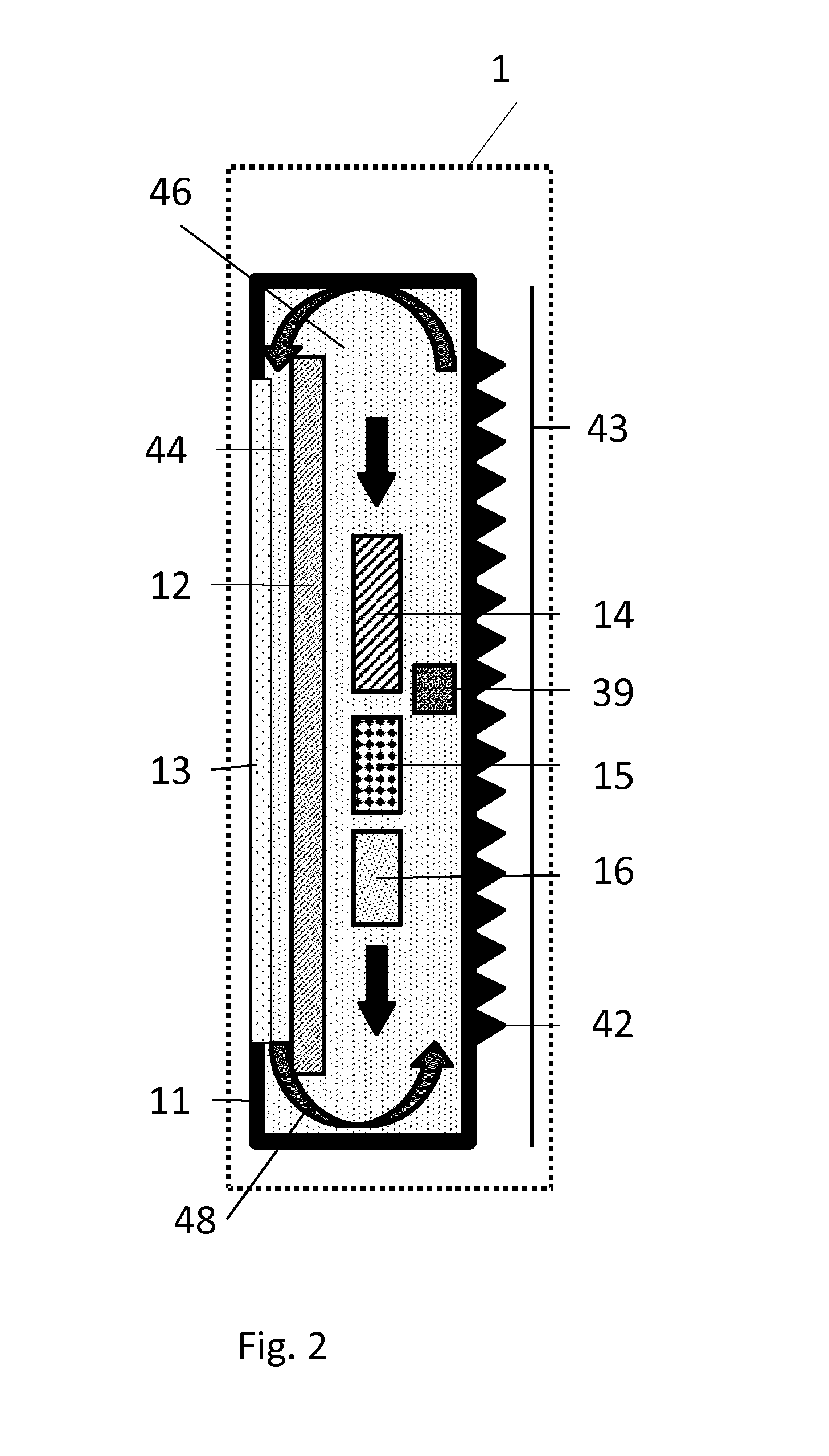
[0035]FIG. 2 schematically shows a second embodiment in accordance with the present invention. The items which have identical reference signs to the items shown in FIGS. 1A and 1B are not discussed anymore. The difference between the embodiment shown in FIG. 2 and the embodiment shown in FIGS. 1A and 1B is that the housing 49 is now the fluid tight encasing 11. The thermal conductive liquid 46 now fills the complete housing 49 of FIGS. 1A and 1B. Consequently, also the electronic circuits 14, the power converter 15 and the optional battery 16 are embedded in the thermal conductive liquid 46. It is not essential for the present invention that the battery 16 is embedded in the thermal conductive liquid. The term embedded does not indicate that the item should be surrounded at all sides by the liquid 46. An optional liquid pump 39 may be present to improve the flow of the thermal conductive liquid 46 inside the fluid tight encasing 11. The pump may be controlled by a thermostatic switc...


PUM


Abstract

A display apparatus comprises a thermal conductive liquid (46) in a liquid tight encasing (11) which has a transparent window (13). A direct view display panel (12) with a front area for displaying information is arranged inside the liquid tight encasing (11) in a position with respect to the transparent window (13) such that the information is viewable through the transparent window (13). The direct view display panel (12) is submerged in the thermal conductive liquid (46).

Description

FIELD OF THE INVENTION[0001]The invention relates to a display apparatus, a digital outdoor advertising system which comprises the display apparatus and a passenger information system which comprises the display apparatus.BACKGROUND OF THE INVENTION[0002]US2012 / 0255721 discloses an outdoor display apparatus which has an improved configuration to effectively prevent deterioration of a panel included therein. The outdoor display apparatus includes: a casing body having an air inlet and an air outlet, first and second display panel modules in the casing body to display images on front and rear surfaces of the casing body, respectively, transparent members fitted respectively to the front surface and the rear surface of the casing body to protect the first and second display panel modules, an air suction unit which comprises a fan to suction the air into the casing body through the inlet via an air filter and to discharge the air through the outlet, and an air distribution unit to distr...

Claims


Application Information

Patent Timeline
IPC IPC(8): H05K7/20H05K5/06H05K5/00
CPCH05K7/20281H05K5/06H05K5/0017G09F9/30G09F19/22G02F1/133385G02F1/133382G02F1/133628
Inventor MAES, MARCEL PETER GERARD
Owner PERMIUM ELECTRONICS CO LTD
Why Eureka
Try Eureka