Combustion liner with bias effusion cooling

Active Publication Date: 2015-11-19
H2 IP UK LTD
View PDF3 Cites 0 Cited by
  • Summary
  • Abstract
  • Description
  • Claims
  • Application Information

AI Technical Summary

Benefits of technology

The present invention provides a better way to cool a combustion liner in order to improve cooling effectiveness and reduce the uneven distribution of cooling air. The combustion liner has an upper and lower portion with a plurality of cooling holes arranged in multiple rows. The lower portion of the annular body has a higher concentration of cooling holes than the upper portion to enhance cooling flow. The cooling pattern includes three sets of axially spaced rows of cooling holes located in the upper, lower, and lower portions of the combustion liner. The third set of cooling holes is positioned between the second and second sets to increase cooling flow to the lower portion of the combustion liner. The technical effect is improved cooling effectiveness and reduced misdistribution of cooling air.

Problems solved by technology

However, a non-uniform distribution of cooling air around the combustion liner can lead to non-uniform cooling, which can cause adverse and undesirable consequences to the structural integrity of the combustion liner.

Method used


Image

  • Combustion liner with bias effusion cooling
  • Combustion liner with bias effusion cooling
  • Combustion liner with bias effusion cooling

Examples


Embodiment Construction

[0025]The subject matter of the present invention is described with specificity herein to meet statutory requirements. However, the description itself is not intended to limit the scope of this patent. Rather, the inventors have contemplated that the claimed subject matter might also be embodied in other ways, to include different components, combinations of components, steps, or combinations of steps similar to the ones described in this document, in conjunction with other present or future technologies.

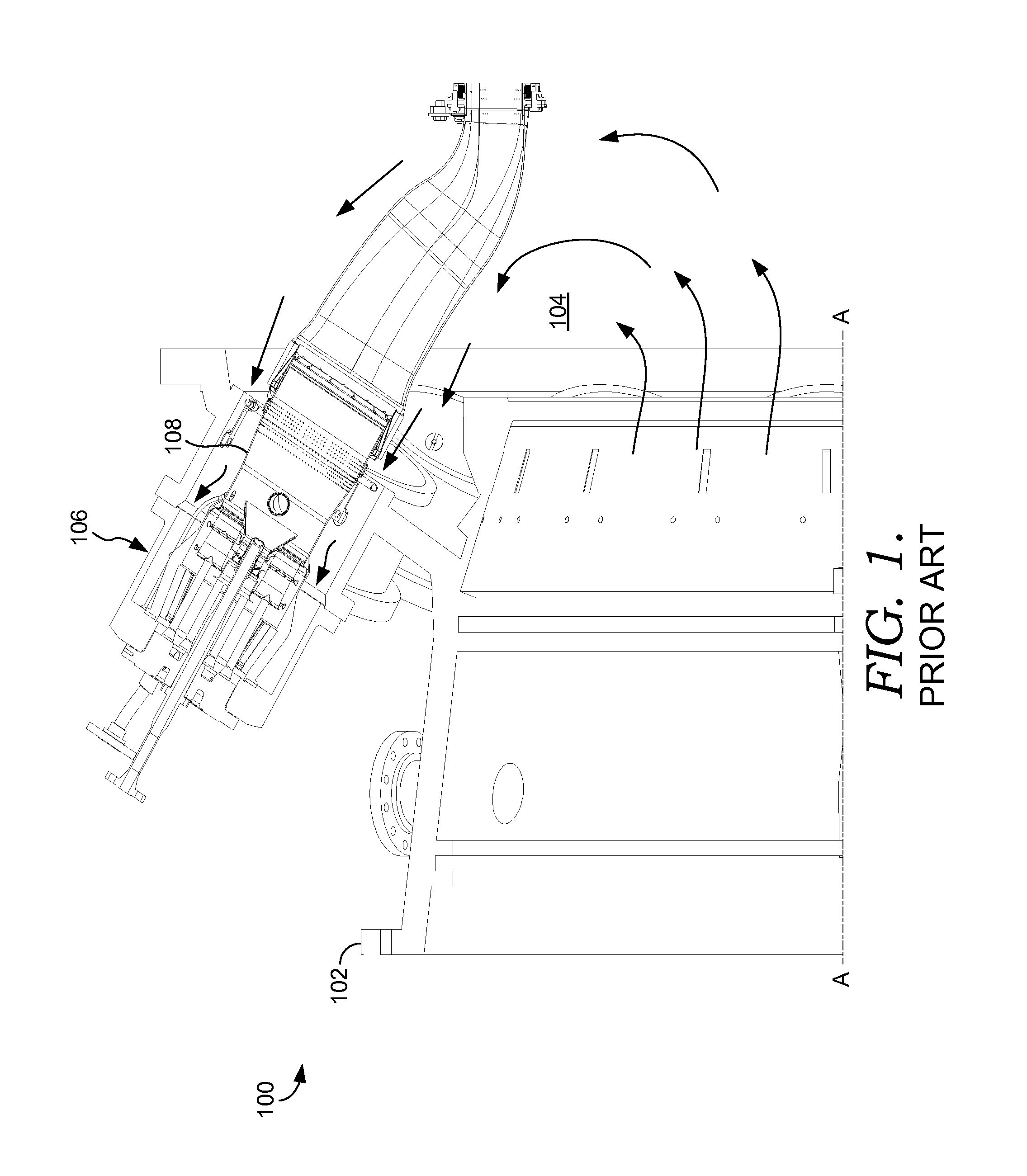
[0026]Referring initially to FIG. 1, a portion of a gas turbine engine 100 of the prior art, and in which an embodiment of the present invention is capable of operating is depicted. The gas turbine engine 100, which operates through a shaft (not shown) extending along an engine axis A-A, includes a compressor case 102 and compressor (not shown) and a compressor discharge plenum 104. The shaft connects the compressor to the turbine. As generally discussed above, the compressor receiv...


PUM


Abstract

A system and method for improving the cooling to a portion of a combustion liner of a gas turbine combustor is disclosed. The combustion liner is cooled by supplying air through a plurality of cooling holes arranged in axially spaced rows in an upper and lower portion of the liner. The cooling holes are spaced accordingly so as to direct additional cooling flow to an area of the combustion liner not receiving sufficient flow due to maldistributions of air from the compressor discharge.

Description

CROSS-REFERENCE TO RELATED APPLICATIONS[0001]None.TECHNICAL FIELD[0002]The present invention generally relates to a gas turbine combustor. More specifically, embodiments of the present invention relate to an apparatus and method for improving the cooling of a combustion liner in order to improve component integrity and operating life.BACKGROUND OF THE INVENTION[0003]In a typical gas turbine engine, a compressor having alternating stages of rotating and stationary airfoils is coupled to a turbine through an axial shaft, with the turbine also having alternating stages of rotating and stationary airfoils. The compressor stages decrease in size in order to compress the air passing therethrough. The compressed air is then supplied to one or more combustors, which mixes the air with fuel. An ignition source in the combustor ignites the mixture, forming hot combustion gases, which then pass through the turbine, expanding and driving the stages of a turbine, which is coupled to the compress...

Claims


Application Information

Patent Timeline
IPC IPC(8): F23R3/04F23R3/00
CPCF23R3/04F23R2900/03041F23R3/002F23R3/06Y02T50/60F23M5/00
Inventor RICHARDSON, BRIANOUMEJJOUD, KHALIDCUTRIGHT, JOHNMCMULLEN, NIKKISTUTTAFORD, PETER JOHNPARKER, RICHARDSONI, SUMIT
Owner H2 IP UK LTD
Why Eureka
Try Eureka