Impingement jet strike channel system within internal cooling systems

a technology of jet strike and cooling system, which is applied in the direction of mechanical equipment, machines/engines, light and heating equipment, etc., can solve problems such as the likelihood of failure, and achieve the effects of enhancing the cooling capacity of the system, and enhancing the jet impingement

Inactive Publication Date: 2018-09-13
SIEMENS ENERGY GLOBAL GMBH & CO KG
View PDF1 Cites 5 Cited by
  • Summary
  • Abstract
  • Description
  • Claims
  • Application Information

AI Technical Summary

Benefits of technology

[0004]An internal cooling system and an impingement jet strike channel system for increasing the effectiveness of impingement jets is disclosed. The impingement jet strike channel system may include an impingement jet strike cavity offset from one or more impingement orifices. A plurality of impingement jet strike channels may extend radially outward from the impingement jet strike cavity forming a starburst pattern of impingement jet strike channels and may be formed by a plurality of ribs that each separate adjacent impingement jet strike channels. The ribs forming the impingement jet strike channels may be split one or more times into multiple channels to increase the number of stagnation points to increase the cooling capacity of the impingement jet strike channel system. The ribs may act as fins, which increases the cooling effectiveness of the impingement jet strike channel system. The plurality of impingement jet strike channels may extend radially outward from the impingement jet strike cavity and may form a starburst pattern of impingement jet strike channels. The impingement jet strike channel system may be used within components, such as, but not limited to, gas turbine engines, including vane inserts, airfoil leading edge cooling systems, platforms, advanced transitions, acoustic resonators, ring segments and the like. In at least one embodiment, the turbine airfoil may be formed from a generally elongated, hollow airfoil having a leading edge, a trailing edge, a pressure side, a suction side, a first end, a second end generally opposite to the first end for supporting the airfoil, and an internal cooling system.
[0005]The internal cooling system may include one or more impingement jet strike channel systems. The impingement jet strike channel system may be formed from a relatively small structure, such as a micro structure, for increasing the effectiveness of the impingement jet strike channel system. In the impingement jet strike channel system, the impingement jet strike cavity may be offset from one or more impingement orifices, whereby the impingement jet strike cavity is defined by surfaces on at least three sides and includes an opening facing the impingement orifice. A plurality of impingement jet strike channels may extend radially outward from the impingement jet strike cavity and may be formed by a plurality of ribs that each separate adjacent impingement jet strike channels. One or more of the plurality of impingement jet strike channels may be divided into first sub-jet strike channels extending radially outward of an inlet of the impingement jet strike channel from a stagnation point created in the impingement jet strike channel at an upstream end of a first sub-rib. In at least one embodiment, each of the plurality of impingement jet strike channels may be divided into first sub-jet strike channels extending radially outward of an inlet of the impingement jet strike channel from a stagnation point created in the impingement jet strike channel at an upstream end of a first sub-rib. The first sub-jet strike channels may be narrower in width than the impingement jet strike channels.

Problems solved by technology

In addition, turbine blades often contain cooling systems for prolonging the life of the blades and reducing the likelihood of failure as a result of excessive temperatures.

Method used


Image

  • Impingement jet strike channel system within internal cooling systems
  • Impingement jet strike channel system within internal cooling systems
  • Impingement jet strike channel system within internal cooling systems

Examples


Embodiment Construction

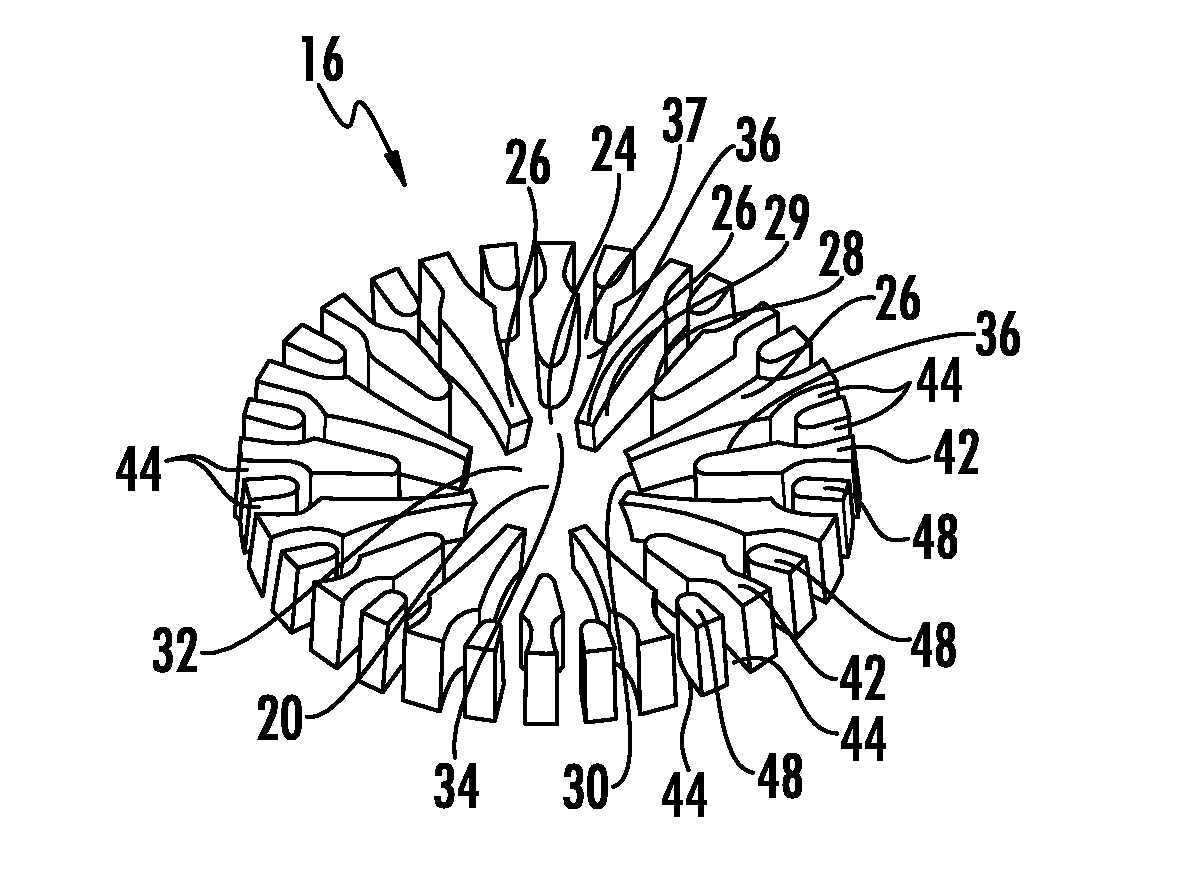
[0039]As shown in FIGS. 1-18, an impingement jet strike channel system 16 for increasing the effectiveness of impingement jets 18 is disclosed. The impingement jet strike channel system 16 may include an impingement jet strike cavity 20 offset from one or more impingement orifices 22. A plurality of impingement jet strike channels 24 may extend radially outward from the impingement jet strike cavity 20 forming a starburst pattern of impingement jet strike channels 24 and may be formed by a plurality of ribs 26 that each separate adjacent impingement jet strike channels 24. The ribs 26 forming the impingement jet strike channels 24 may be split one or more times into multiple channels 24 to increase the number of stagnation points 28 to increase the cooling capacity of the impingement jet strike channel system 16. The ribs 26 may act as fins, which increases the cooling effectiveness of the impingement jet strike channel system 16. The impingement jet strike channel system 16 may be ...


PUM


Abstract

An internal cooling system (14) including an impingement jet strike channel system (16) for increasing the effectiveness of impingement jets (18) is disclosed. The impingement jet strike channel system (16) may include an impingement jet strike cavity (20) offset from one or more impingement orifices (22). A plurality of impingement jet strike channels (24) may extend radially outward from the impingement jet strike cavity (20) forming a starburst pattern of impingement jet strike channels (24) and may be formed by a plurality of ribs (26) that each separate adjacent impingement jet strike channels (24). The ribs (26) forming the impingement jet strike channels (24) may be split one or more times into multiple channels to increase the number of stagnation points (28, 38, 52) to increase the cooling capacity. The impingement jet strike channel system (16) may be used within components, such as, but not limited to, gas turbine engines (12), including vane inserts, airfoil leading edge cooling systems, platforms, advanced transitions, acoustic resonators, ring segments and the like.

Description

FIELD OF THE INVENTION[0001]This invention is directed generally to cooling systems, and more particularly to cooling system usable within structures exposed to high temperatures, such as, but not limited to cooling system in hollow airfoils of turbine engines.BACKGROUND[0002]Typically, gas turbine engines include a compressor for compressing air, a combustor for mixing the compressed air with fuel and igniting the mixture, and a turbine blade assembly for producing power. Combustors often operate at high temperatures that may exceed 2,500 degrees Fahrenheit. Typical turbine combustor configurations expose turbine blade assemblies to these high temperatures. As a result, turbine blades must be made of materials capable of withstanding such high temperatures. In addition, turbine blades often contain cooling systems for prolonging the life of the blades and reducing the likelihood of failure as a result of excessive temperatures.[0003]Internal cooling systems often include a pluralit...

Claims


Application Information

Patent Timeline
Patent Type & Authority Applications(United States)
IPC IPC(8): F01D5/18F01D25/12F28F13/12
CPCF01D5/187F01D25/12F28F13/12F05D2240/303F05D2260/201F05D2260/22141F05D2250/32F05D2250/711F05D2220/32F28F2210/02
Inventor ZUNIGA, HUMBERTO A.
Owner SIEMENS ENERGY GLOBAL GMBH & CO KG
Why Eureka
Try Eureka