Manufacturing aligned cooling features in a core for casting

Pending Publication Date: 2022-06-23
SIEMENS ENERGY GLOBAL GMBH & CO KG
View PDF0 Cites 0 Cited by
  • Summary
  • Abstract
  • Description
  • Claims
  • Application Information

AI Technical Summary

Benefits of technology

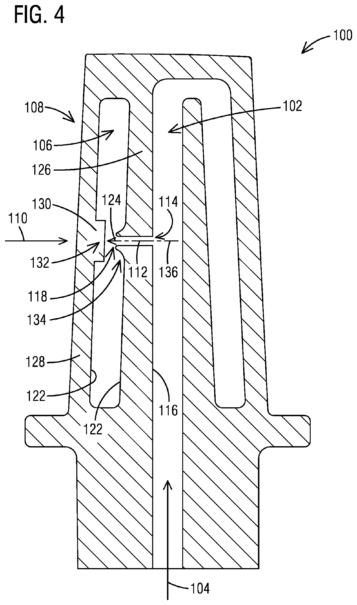
[0007]In another aspect of the present invention, an impingement cooling system for a gas turbine engine component includes a coolant cavity positioned within the gas turbine engine component receiving a flow of a cooling fluid, an impingement cavity positioned within the gas turbine engine component comprising an impingement cooled surface side, for exposure to a hot gas flow; an impingement jet wall separating the cooling cavity from the impingement cavity, the impingement jet wall comprising at least one a crossover hole having a cooling fluid inlet at a cooling fluid receiving side for receiving at least a portion of a cooling fluid and discharging a directed jet of the at least portion of the cooling fluid from a cooling fluid outlet at a cooling fluid jetting side and further comprising an impingement jet conditioning feature at the cooling fluid jetting side for con

Problems solved by technology

Typically, thermal barrier coatings (TBC's) are applied to exterior surfaces of the airfoils to protect them from exposure to high temperatures, but such coating may be subject to spallation over time, especially on the airfoil leading edges.
In addition, turbine blades often contain cooling systems for prolonging the life of the airf

Method used


Image

  • Manufacturing aligned cooling features in a core for casting
  • Manufacturing aligned cooling features in a core for casting

Examples


Embodiment Construction

[0013]In the following detailed description of the preferred embodiment, reference is made to the accompanying drawings that form a part hereof, and in which is shown by way of illustration, and not by way of limitation, a specific embodiment in which the invention may be practiced. It is to be understood that other embodiments may be utilized and that changes may be made without departing from the spirit and scope of the present invention.

[0014]Gas turbine airfoil TBC degradation and spallation is most prevalent on the leading edges of the airfoils. Cooling fluid impingement jets directed at the backside of the leading edge from a serpentine cooling passage are commonly used to cool the leading edge, consequently improving the life and spallation resistance of the airfoil.

[0015]In addition, impingement features formed on the backside of hot gas path components, such as described in US published patent application 20180258773 and PCT published patent application WO2018044266A1, can ...


PUM


Abstract

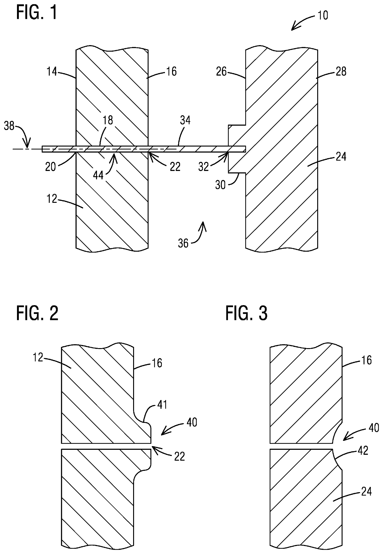
A molding tool (10) for manufacturing cooling features in a ceramic core for a casting process includes a first mold portion (12) comprising a crossover hole forming feature (18); a second mold portion (24) comprising an impingement jet receiving forming feature (30) for forming an impingement jet receiving feature having a desired aiming point (32); and a sacrificial alignment member (34) for extending at least partially into the crossover hole forming feature (18) at least partially into the aiming point (32) of the impingement jet receiving forming feature (30) for substantially aligning a central axis (38) of the crossover hole forming feature (18) with the aiming point (32) to maintain a crossover hole and aiming point alignment during casting to ensure that the jet is directed at the aiming point (32) in a resultant cast part.

Description

BACKGROUND1. Field[0001]The present invention relates to a method of manufacturing advanced features in a core for casting.2. Description of the Related Art[0002]Typically, gas turbine engines include a compressor for compressing air, a combustor for mixing the compressed air with fuel and igniting the mixture, and turbine airfoils for producing power. Combustors often operate at high temperatures that may exceed 2,500 degrees Fahrenheit. Typical turbine combustor configurations expose turbine airfoils to these high temperatures. As a result, turbine airfoils and must be made of materials capable of withstanding such high temperatures. Typically, thermal barrier coatings (TBC's) are applied to exterior surfaces of the airfoils to protect them from exposure to high temperatures, but such coating may be subject to spallation over time, especially on the airfoil leading edges.[0003]In addition, turbine blades often contain cooling systems for prolonging the life of the airfoils and red...

Claims


Application Information

Patent Timeline
IPC IPC(8): B22C13/12B22C13/08B22C9/10B22C9/04F01D5/18B22C9/06
CPCB22C13/12B22C13/08B22C9/10F05D2230/21F01D5/187B22C9/065B22C9/04F01D5/186
Inventor MERRILL, GARY B.RODRIGUEZ, JOSE L.DORAN, IAN T.
Owner SIEMENS ENERGY GLOBAL GMBH & CO KG
Why Eureka
Try Eureka