Platform segment for supporting a nozzle guide vane for a gas turbine and nozzle guide vane arrangement for a gas turbine

a technology for gas turbines and platform segments, which is applied in the direction of machines/engines, stators, liquid fuel engines, etc., can solve the problems of reducing the performance and/or durability of gas turbines, and the platform segment may be adversely affected, so as to improve heat transfer and heat transfer. , the effect of channelling to the downstream portion of the cooling surfa

Inactive Publication Date: 2013-08-15
SIEMENS AG
View PDF1 Cites 16 Cited by
  • Summary
  • Abstract
  • Description
  • Claims
  • Application Information

AI Technical Summary

Benefits of technology

[0034]The further wall protruding from the cooling surface and extends at least partially in a direction of the streaming gas, wherein a circumferential distance between the wall and the further wall decreases along the streaming direction. Thus, the width of a channel limited by the wall and the further wall decreases from the upstream portion of the cooling surface to the downstream portion of the cooling surface. The decrease of the width of the channel may be in correspondence to a decrease of a cross-sectional width of the nozzle guide vane arranged circumferentially spaced apart from the channel (but at similar axial position). By the further wall the channelling to the downstream portion of the cooling surface may even be improved, thus improving heat transfer from the downstream portion of the cooling surface and thus also improving heat transfer away from the downstream portion of the gas passage surface to the cooling fluid.
[0035]According to an embodiment the turbulator extends from the wall to the further wall. Thus, the turbulator increases the turbulence of the cooling fluid in the whole region between the wall and the further wall for effectively causing or enhancing turbulence of the cooling fluid.
[0036]According to an embodiment the platform segment further comprises a cover arranged (in particular oppositely to the cooling surface) to be in contact with portions of the wall and the further wall protruding to a maximal extent from the cooling surface, thereby covering the cooling surface between the wall and the further wall. The cover may also be referred to as impingement plate, although the cover may not have a planar shape. In particular, the cover may comprise a shape having at least partially cylindrical symmetry. The cover may in particular close the channel formed between the wall and the further wall for even more effectively channelling the cooling fluid. In particular, the cover may comprise one or more holes through which the cooling fluid may enter the space between the cooling surface and a surface of the cover being in contact with at least portions of the wall and the further wall. Depending on cooling requirements the number and locations of the holes in the cover may be appropriately adjusted.
[0037]According to an embodiment the wall comprises a section protruding from the cooling surface to a maximal extent and a section protruding from the cooling surface between 0.2 times and 0.8 times, in particular between 0.4 times and 0.6 times, the maximal extent. Thereby, a so-called castellated wall may be provided. Also the further wall may be structured in a similar way. Thereby, in particular the portion of maximal protrusion extent may contact the cover, while the portion having a protrusion extent smaller than the maximal protrusion extent may not contact the cover. Thereby, openings between adjacent channels formed by the wall and the further wall may be provided which may allow the cooling fluid to exchange between adjacent channels such that an equal pressure of the cooling fluid may be ensured across all regions of the cavity between the cover and the cooling surface. Thereby, the cooling effectiveness may be improved.

Problems solved by technology

Thereby, the material from which the platform segment is manufactured may be chemically altered and / or mechanically altered such that the platform segment may be adversely effected, such as by extensive oxidation.
The oxidation may then lead to a reduced performance and / or durability of the gas turbine.

Method used


Image

  • Platform segment for supporting a nozzle guide vane for a gas turbine and nozzle guide vane arrangement for a gas turbine
  • Platform segment for supporting a nozzle guide vane for a gas turbine and nozzle guide vane arrangement for a gas turbine
  • Platform segment for supporting a nozzle guide vane for a gas turbine and nozzle guide vane arrangement for a gas turbine

Examples


Embodiment Construction

[0054]The illustration in the drawing is schematically. It is noted that in different figures, similar or identical elements are provided with the same reference signs or with reference signs, which are different from the corresponding reference signs only within the first digit.

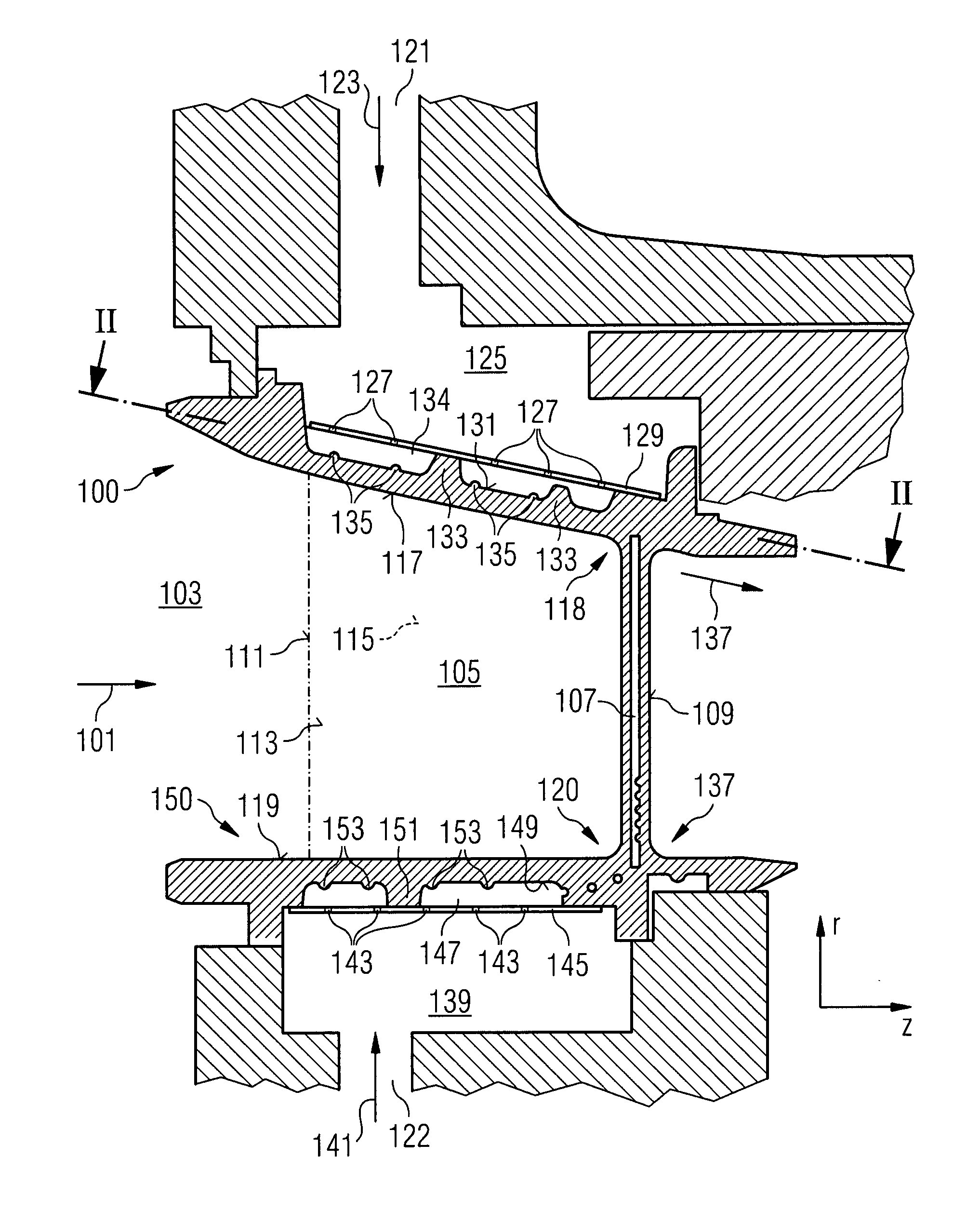
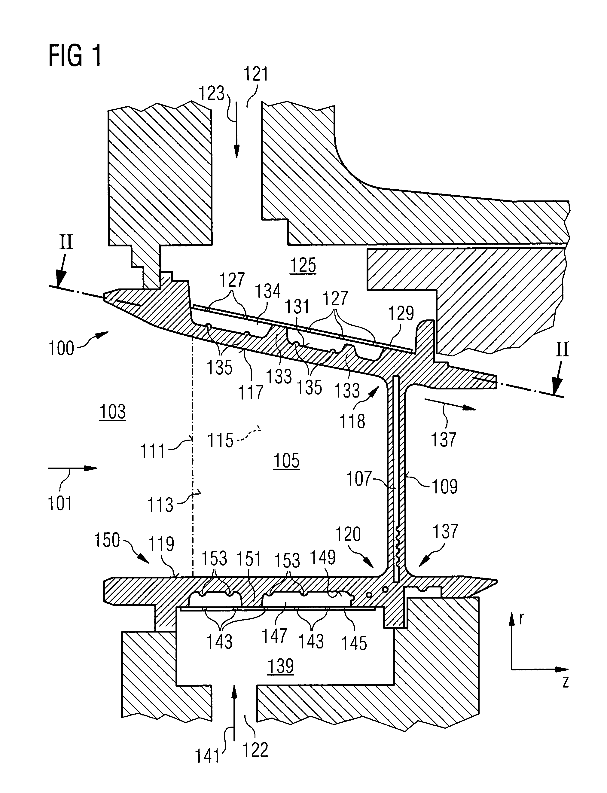
[0055]FIG. 1 schematically illustrates a cross-sectional view of a portion of a gas turbine including a radially outer platform segment 100 for supporting a nozzle guide vane according to an embodiment and a radially inner platform segment 150 for supporting a nozzle guide vane according to an embodiment. An operation gas exhausted from a combustor upstream of the outer platform segment 100 and the inner platform segment 150 propagates along a direction indicated by reference sign 101. A not indicated rotation axis lies within the drawing plane of FIG. 1 in a horizontal orientation.

[0056]By the direction 101 of the streaming or flowing operation gas an upstream side of a component of the turbine may be defin...


PUM


Abstract

A platform segment for supporting a nozzle guide vane for a gas turbine is provided. The platform segment includes a gas passage surface arranged to be in contact with a streaming gas exhausted from a combustor, wherein the streaming gas streams along the gas passage surface in a streaming direction, a cooling surface, opposite to and thermally connected to the gas passage surface and arranged to be in contact with a cooling fluid, a wall protruding from the cooling surface and extending at least partially in the streaming direction, wherein the wall is arranged circumferentially between positions, at which adjacent guide vanes are to be provided, such that cooling fluid is channeled by the wall for cooling a downstream portion of the cooling surface, and a further wall protruding from the cooling surface and extending at least partially in the streaming direction.

Description

CROSS REFERENCE TO RELATED APPLICATIONS[0001]This application is the US National Stage of International Application No. PCT / EP2011 / 058910, filed May 31, 2011 and claims the benefit thereof. The International Application claims the benefits of European Patent Office application No. 10166299.7 EP filed Jun. 17, 2010. All of the applications are incorporated by reference herein in their entirety.FIELD OF INVENTION[0002]The present invention relates to a platform segment for supporting a nozzle guide vane for a gas turbine and to a nozzle guide vane arrangement for a gas turbine, wherein a cooling surface is provided at the platform segment for cooling at least a portion of the platform segment. Further, the present invention relates to a method for cooling a nozzle guide vane platform segment by using a cooling fluid channelled for cooling at least a portion of the nozzle guide vane platform segment.ART BACKGROUND[0003]A nozzle guide vane is a static segment of a gas turbine which guid...

Claims


Application Information

Patent Timeline
Patent Type & Authority Applications(United States)
IPC IPC(8): F01D9/02
CPCF01D9/041F05D2260/201F01D9/023F05D2240/127F05D2240/81F05D2260/2212
Inventor BUTLER, DAVIDDAVIS, ANTHONYPOOLE, CHARLOTTEWALKER, PAUL MATTHEW
Owner SIEMENS AG
Why Eureka
Try Eureka