Contact heat-transferring cooking system with an electric hotplate

a technology of electric hotplates and cooking systems, which is applied in the direction of domestic stoves or ranges, heating types, lighting and heating apparatuses, etc., can solve the problems of low efficiency of radiant heaters and has not yet acquired practical application

Inactive Publication Date: 2000-11-21
E G O ELEKTRO GERAETEBAU GMBH
View PDF29 Cites 110 Cited by
  • Summary
  • Abstract
  • Description
  • Claims
  • Application Information

AI Technical Summary

Benefits of technology

As a result of these measures an extremely good heat transfer is ensured. As a result the temperature difference between the hotplate surface and the saucepan bottom can be very small even with higher power densities. The electric hotplate does not need to be significantly hotter than the product being cooked, because hitherto in the case of contact heat-transferring hotplates the air gaps formed between the cooking surface of the electric hotplate and the saucepan bottom determined the relatively high temperature difference between the hotplate and the cooking product. However, the temperature differences in the material of the electric hotplate and the saucepan largely determined by heat conduction are almost negligible. As for the indicated, adapted conditions, the temperature difference in the "microgap" possibly forming are very small due to the limited gap size and in the range of a few K, with regards to the heat transfer there is scarcely a difference compared with the ideal contact between both surfaces. As a result heat is very uniformly taken from the electric hotplate and supplied to the cooking vessel. As a result the hotplate no longer has to distribute heat and the saucepan bottom is very uniformly heated, so that there is an avoidance of local temperature differences, which can lead to a non-uniform cooking result over the surface.
For an energy saving and rapidly regulatable cooking system the stored energy of the hotplate body is important. Relative to the installed capacity of the hotplate it should be between 7 and 130 J / W, preferably between 10 and 50 J / W. Particularly on heating up, only a limited energy quantity is required to bring the plate to a working temperature. However, here again an important part is played by the fact that the hotplate body itself does not have to assume such a high temperature in order to pass on the heat to the cooking product.
It is also possible to successfully work with flame spraying processes, which can also operate with plasma. In this way it is possible to spray an intermediate film of a material serving as a primer and / or electrical insulation, e.g. aluminium oxide (Al.sub.2 O.sub.3). An electrical insulation can be particularly important when using an electrically conductive ceramic, e.g. silicon carbide.
Below the heating system can be placed a thermal insulation layer, the latter at all events having a supporting function. However, the hob plate is advantageously self-supporting.
The invention provides a cooking system able to operate with extremely high efficiencies. This is a result of the very good thermal coupling of the cooking vessel and its content with the heating system with limited temperature differences between the same and the fact that such a heating procedure has very low mass and storage. This has a particular effect on the heating up efficiencies, which in the case of conventional, cast iron contact hotplates are 60%, in glass ceramic radiant cooking systems 70% and in induction hot points with their high demands regarding technology and cooking vessels 80%. However, heating up efficiencies of 90% can be achieved with the cooking system according to the invention. Another important advantage are the low maximum temperatures at the hotplate and heating system only a little above the cooking product temperatures. When cooking water-containing foods they are consequently not much over 100.degree. C., whereas when roasting or frying in boiling oil they do not normally exceed 350.degree. C.

Problems solved by technology

However, due to their material they have relatively long heating up periods, resulting, if only the heating up operation is considered, in lower efficiencies than radiant heaters and induction-based systems.
However, they have not as yet acquired practical application.

Method used


Image

  • Contact heat-transferring cooking system with an electric hotplate
  • Contact heat-transferring cooking system with an electric hotplate
  • Contact heat-transferring cooking system with an electric hotplate

Examples


Embodiment Construction

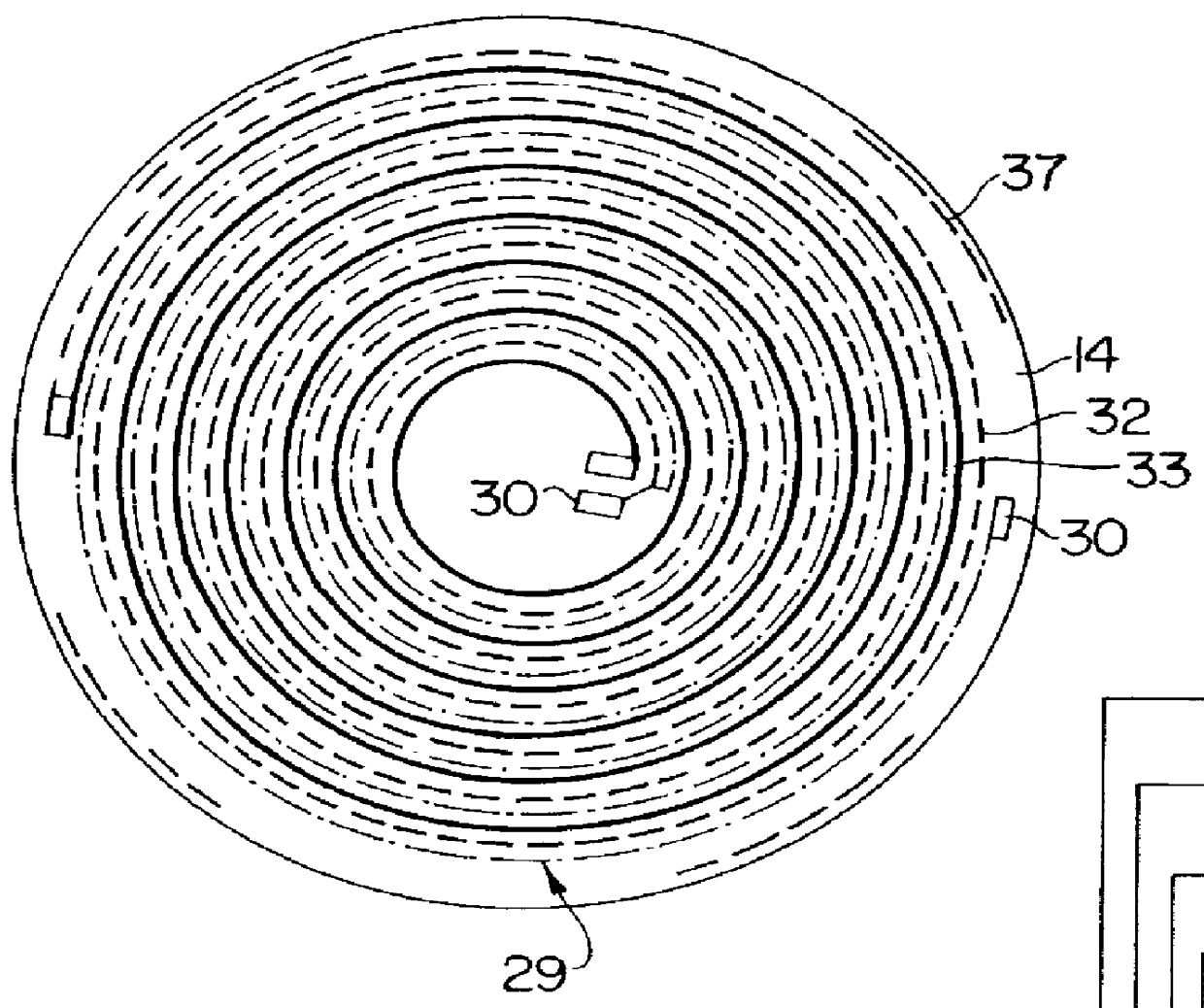
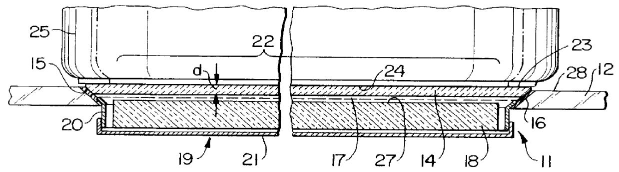
FIG. 1 shows a cooking system with an electric hotplate 11, whereof one or more are installed in a hob plate 12 of an electric cooker, electric hob, etc., which can in turn be placed in a work plate 13 (FIGS. 21 and 22) of a kitchen furniture item.

An essential component of the electric hotplate is a hotplate body 14. It comprises a usually circular (FIG. 2) disk of nonoxidic ceramic, preferably sintered silicon nitride (Si.sub.3 N.sub.4). Other materials are possible, provided that they are able to respect the aforementioned and in part also subsequently illustrated mechanical, thermal and electrical characteristics. The plate thickness should be between 2 and 4 mm.

On the outer edge or rim 15 the disk-shaped hotplate body 14 has a conical construction, so as to taper downwards. This conical outer rim 15 matches a corresponding conical opening rim 16 of the hob plate 12. Details of the installation will be given hereinafter relative to FIGS. 9 to 16.

On the underside of the hotplate b...


PUM


Abstract

A contact heat-transferring electric hotplate (11) is provided, which is made from nonoxidic ceramic, particularly silicon nitride. Its very thin hotplate body (14) in the form of a disk is installed in self-supporting manner in a hob plate, e.g. by bonding, and has an extremely flat surface or which is adapted to the cooking vessel shape, which creates such a small gap with respect to said vessel that a coupling is possible even with higher power densities with only a temperature difference of a few degrees. The heating means (17) is also in contact with or directly connected to the underside of the hotplate body (14).

Description

FIELD OF APPLICATION AND PRIOR ARTAt present three cooking system types are known, which heat a cooking vessel standing on a plate essentially from below. These involve cast iron hotplates, which transfer the heat mainly by thermal contact to the cooking vessels, radiant heating cooking implements, in which the radiant heater members are placed below a glass ceramic plate, and induction hotplates, which transfer the energy into the bottom of the saucepan through induction fields. Cast hotplates have proved satisfactory for more than half a century and are virtually without compare as regards robustness, reliability and versatility of control. However, due to their material they have relatively long heating up periods, resulting, if only the heating up operation is considered, in lower efficiencies than radiant heaters and induction-based systems.Contact-based electric hotplates made from ceramic material have already been proposed, which are better than cast hotplates with regards t...

Claims


Application Information

Patent Timeline
Patent Type & Authority Patents(United States)
IPC IPC(8): A47J27/00F24C15/10H05B3/68H05B3/74H05B6/12A47J36/02
CPCA47J27/002F24C15/102H05B3/748Y02B30/26H05B2213/07Y02B30/00
Inventor BOGDANSKI, FRANZOSE, LUTZ
Owner E G O ELEKTRO GERAETEBAU GMBH
Why Eureka
Try Eureka