Method and Apparatus for Sensing Environment Using a Wireless Passive Sensor

a passive sensor and environment technology, applied in the field of sensing a detectable environment condition in a passive rfid system, to avoid unnecessary proliferation of numbers

a passive sensor and environment technology, applied in the field of sensing a detectable environment condition in a passive rfid system, to avoid unnecessary proliferation of numbers

US20160188927A1Active Publication Date: 2016-06-30RFMICRON

Image

  • Method and Apparatus for Sensing Environment Using a Wireless Passive Sensor
  • Method and Apparatus for Sensing Environment Using a Wireless Passive Sensor
  • Method and Apparatus for Sensing Environment Using a Wireless Passive Sensor

Examples


Embodiment Construction

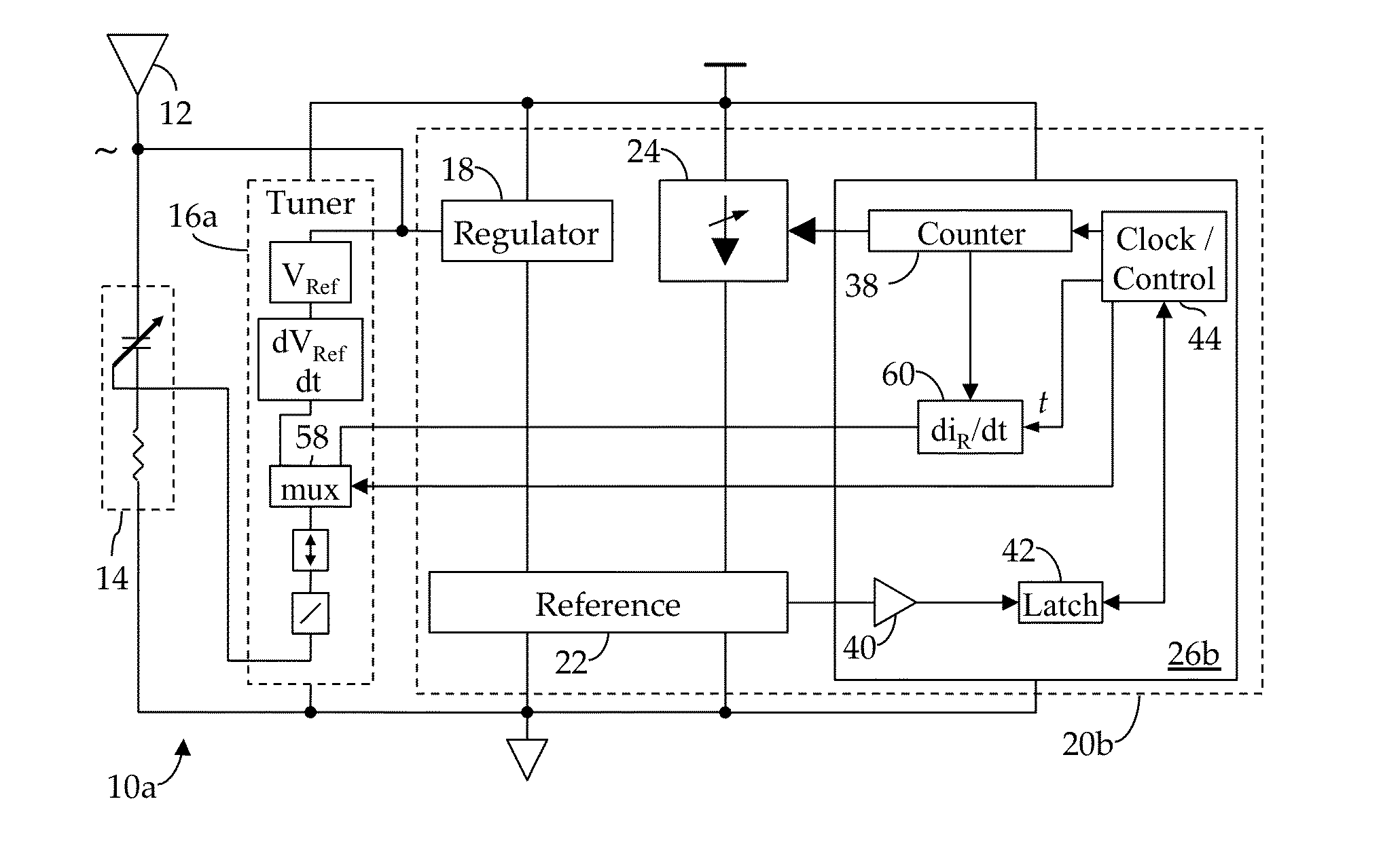
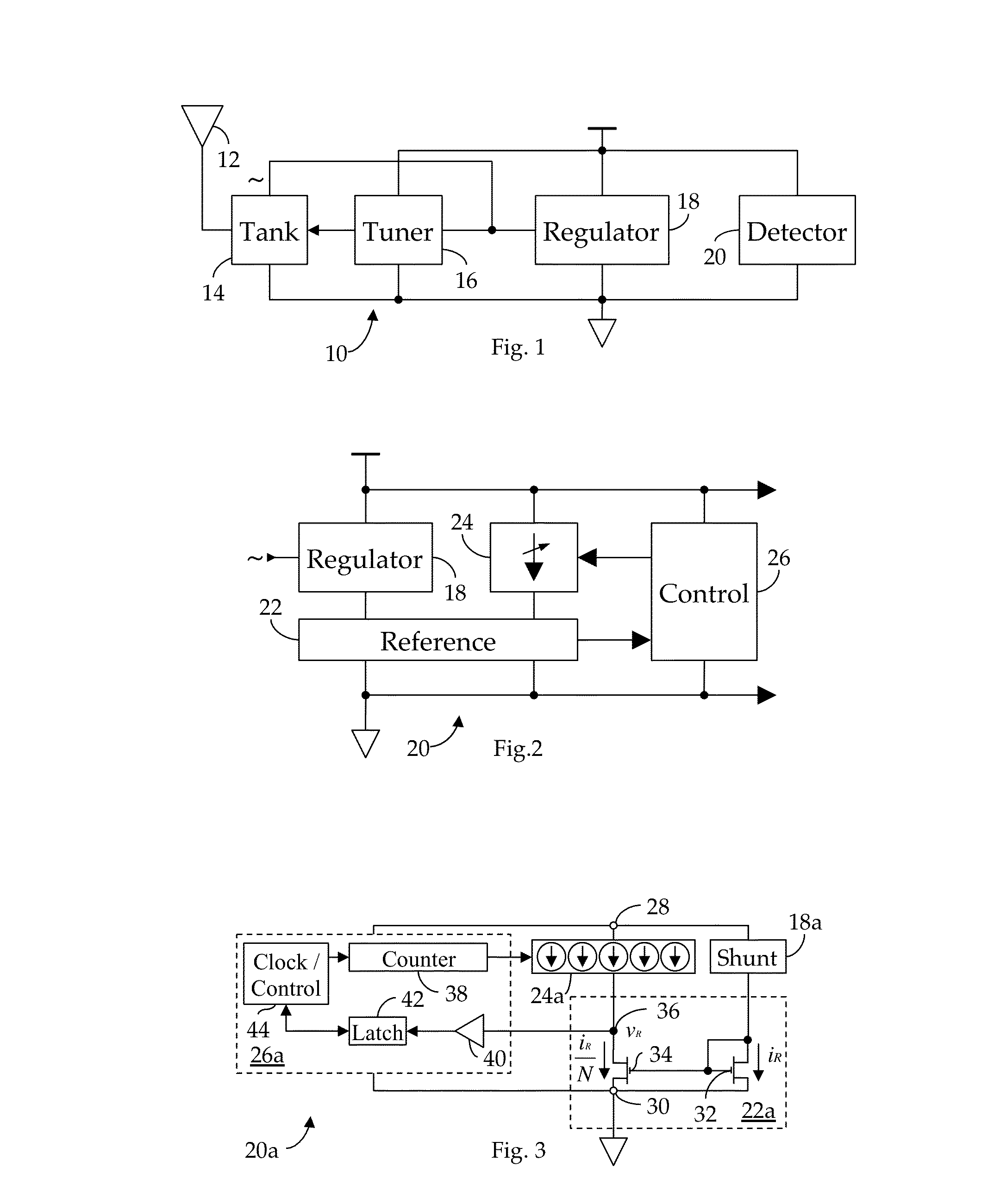
[0036]Shown in FIG. 1 is an RF receiver circuit 10 suitable for use in an RFID application. As we have described in our Related References, an RF signal electromagnetically coupled to an antenna 12 is received via a tank circuit 14, the response frequency, fR, of which is dynamically varied by a tuner 16 to better match the transmission frequency, fC, of the received RF signal, thus obtaining a maximum power transfer. In particular, as further noted in the Related Applications, the RMS voltage induced across the tank circuit 14 by the received RF signal is quantized by tuner 16 and the developed quantization employed to control the impedance of the tank circuit 14. As also described in the Related References, the unregulated, AC current induced in the tank circuit 14 by the received RF signal is conditioned by a regulator 18 to provide regulated DC operating power to the receiver circuit 10. In accordance with our present invention, we now provide a field strength detector 20, also ...


PUM


Abstract

A method and apparatus for detecting RF field strength. A field strength reference generator develops a field strength reference current as a function of a field strength of a received RF signal; and a field strength quantizer develops a digital field-strength value indicative of the field strength reference current. In one embodiment, detected field strength is used to dynamically vary the impedance of a tank circuit whereby, over time, induced current is maximized. In another embodiment, the quantized field strength is used to sense changes to the environment to which the RFID tag is exposed. In yet another embodiment, dynamic variations of the quantized impedance of the tank circuit are used to sense changes in the environment. Several alternate antennas are specially adapted to facilitate sensing of environmental conditions using the RFID tag.

Description

CROSS-REFERENCE TO RELATED APPLICATIONS[0001]This application is a Continuation-In-Part of application Ser. No. 13 / 209,420, filed 14 Aug. 2011 (“Parent Application One”), which claims priority to U.S. Provisional Application Ser. No. 61 / 428,170, filed 29 Dec. 2010 (“Parent Provisional One”) and U.S. Provisional Application Ser. No. 61 / 485,732, filed 23 May 2011 (“Parent Provisional Two”). Parent Application One is, in turn, a Continuation-In-Part of application Ser. No. 12 / 462,331, filed 1 Aug. 2009, which is now U.S. Pat. No. 8,081,043, issued 20 Dec. 2011 (“Parent Patent One”).[0002]This application is also a Continuation-In-Part of application Ser. No. 13 / 467,925, filed 9 May 2012 (“Parent Application Two”), which claims priority to Parent Provisional Two.[0003]This application is also a Continuation-In-Part of application Ser. No. 13 / 209,425, filed simultaneously with the Parent Application One on 14 Aug. 2011 (“Related Co-application”).[0004]This application claims priority to:...

Claims


Application Information

Patent Timeline
30 Jun 2016
Publication
US20160188927A1
IPC
G06K7/10; G06K19/07
CPC
G06K7/10366; G06K19/0723; G06K7/10346; G06K7/10316; G06K19/0716; H03J3/20; H03J2200/10; H04B5/79
Inventors
ROKHSAZ, SHAHRIAR; YOUNG, BRIAN DAVID