Projectile

a projectile and projectile technology, applied in the field of projectiles, can solve the problems of projectiles which permanently deform unrepresentatively, ballistic tests often fail to take into account the nature of blade impact the impact angle of known ballistic test methods is not taken into account in terms of impact angle and loading, so as to facilitate sabot release, reduce debris, and minimize the effect of projectile retardation

Active Publication Date: 2016-07-14
ROLLS ROYCE PLC
View PDF7 Cites 4 Cited by
  • Summary
  • Abstract
  • Description
  • Claims
  • Application Information

AI Technical Summary

Benefits of technology

The patent describes a new type of projectile that can mimic different sizes and stages of blade impacts. The projectile has an ellipsoid shape that increases the energy density of impact and provides stability during flight. The projectile can also have a coating for easy identification and to represent the interaction with the fan blade. The outer surface of the projectile can have a patterned coating to further aid in identifying it. The weight adjustment body in the projectile allows for controlled movement and can be used to control the impact forces. A sabot is used to release the projectile and minimize retardation and debris. This new design provides a more accurate and precise tool for simulating blade impacts.

Problems solved by technology

These known ballistic test methods fail to take account of the nature of blade impact in terms of impact angle and loading.
Ballistic tests often fail to replicate these impact angles and feature projectiles which permanently deform unrepresentatively due to differences between a rotating and linearly translating projectile.

Method used


Image

  • Projectile
  • Projectile
  • Projectile

Examples


Embodiment Construction

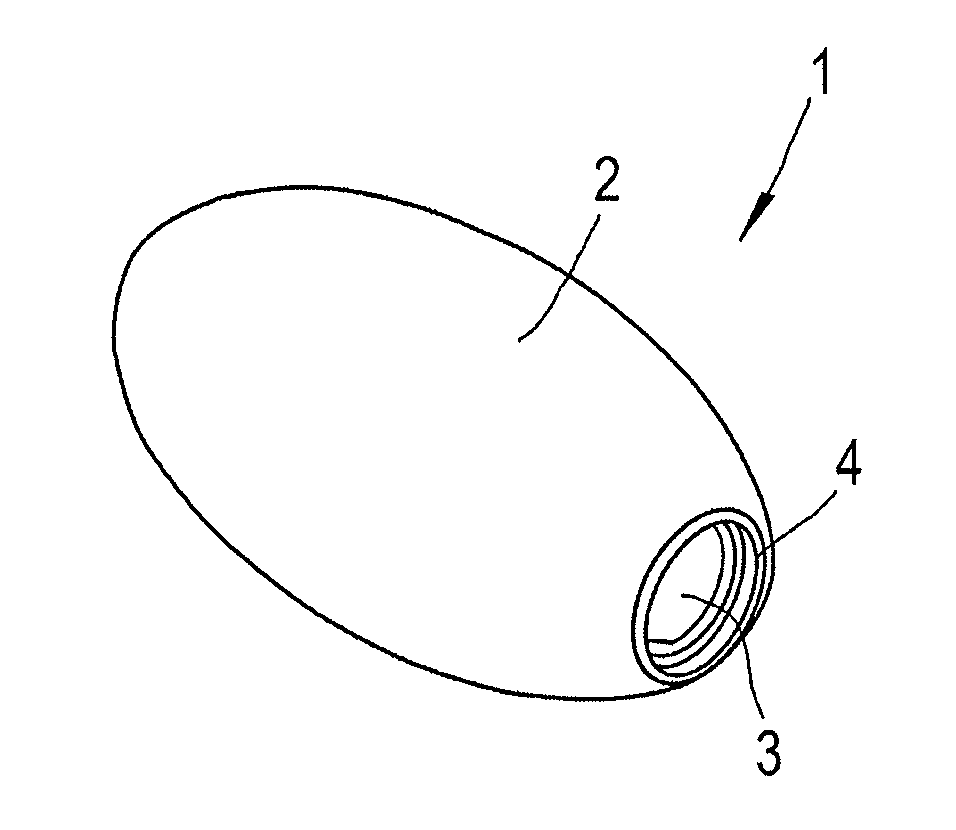
[0049]FIGS. 1 to 5 show a projectile 1 for use in a simulated fan-blade-off ballistic test. The projectile has an ellipsoid body 2 having a blind axial bore 3 extending from a first axial end 4, the blind axial bore 3 for housing a weight adjustment body 9 (shown in FIGS. 5 and 6).

[0050]The first axial end 4 is truncated where the axial bore is formed.

[0051]The axial length of the ellipsoid body 2 (i.e. the distance from the first axial end 4 to the second axial end 5) is around 170 mm.

[0052]The length of the axial bore 3 (i.e. the distance from the first axial end 4 to the blind end 6 of the bore 3 is around 164 mm.

[0053]The diameter of the ellipsoid body 2 is around 90 mm.

[0054]The diameter of the axial bore 3 is around 26.6 mm. The axial bore 3 has an enlarged diameter section 7 (e.g. having a diameter around 35 mm) proximal the first axial end 4. An intermediate diameter section 8 is provided between the enlarged diameter section 7 and the main axial bore 3. The intermediate sec...


PUM


Abstract

The present invention provides a projectile for use in a simulated fan-blade-off ballistic test. The projectile has an ellipsoid body having a blind axial bore extending from a first axial end. The blind axial bore is for housing a weight adjustment body which can be used to modify the weight and / or centre of gravity of the projectile. A sealing plug may seal the weight adjustment body within the axial bore and an insert may be provided to fix the position of the weight adjustment body and / or to control the sliding of the weight adjustment body within the axial bore.

Description

FIELD OF THE INVENTION[0001]The present invention relates to a projectile for use in an improved fan-blade-off ballistic simulation test method.BACKGROUND OF THE INVENTION[0002]The aviation authority requires that gas turbine engine casings must be capable of containing the release of a single or multiple compressor or turbine blade(s). The “fan-blade-off” test is a single-shot test where a projectile is released explosively and the mechanical integrity of all systems and the containment capability of the engine casing is assessed following the projectile release.[0003]The projectile is typically a fan blade (full sized or scaled) or a fan blade fragment.[0004]The test may be an engine test or a rig test which are expensive and require long lead times. Often a reduced cost but complex ballistic test is used to simulate the fan-blade-off-test.[0005]These known ballistic test methods fail to take account of the nature of blade impact in terms of impact angle and loading. In real-life ...

Claims


Application Information

Patent Timeline
IPC IPC(8): F42B12/02G01N3/30
CPCG01N3/30F42B12/02F42B8/12F42B30/00
InventorWILLIAMS, CHRISTOPHERFINLAYSON, JAMES
OwnerROLLS ROYCE PLC