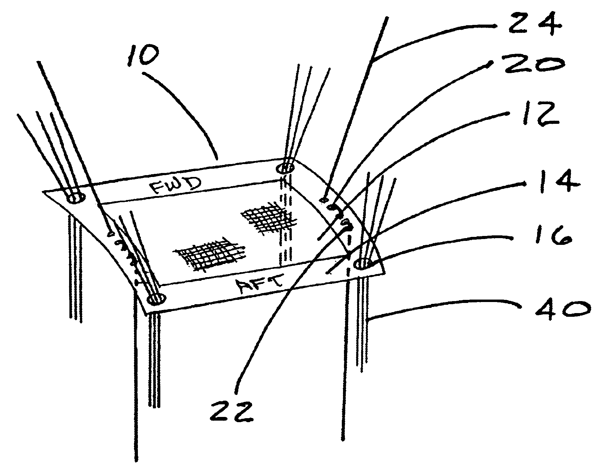
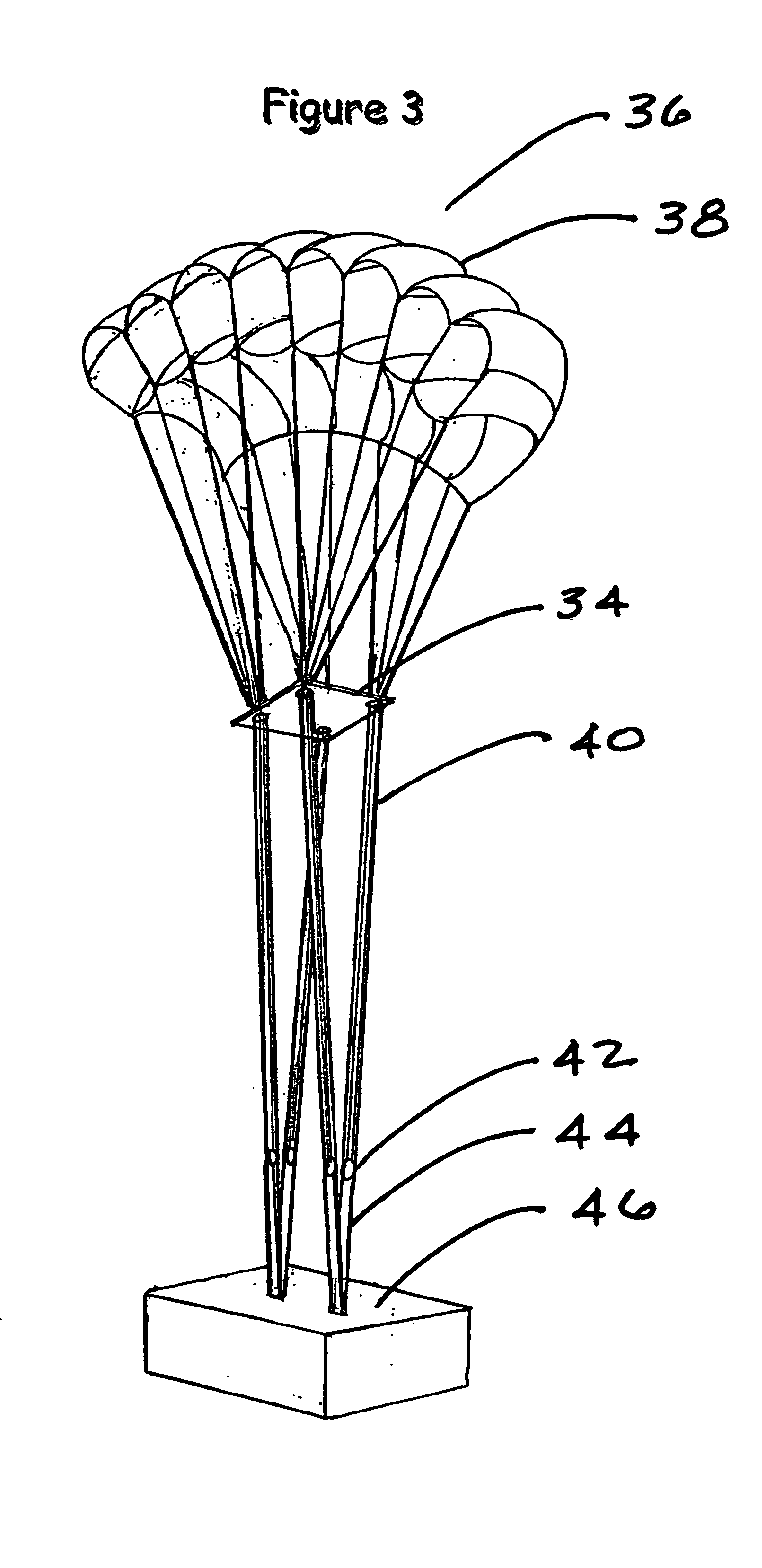
In accordance with the present invention, there is provided a novel reefing slider enhancement that is distinguished by being significantly less dependent on aerodynamic forces than has been exhibited by the prior art and can, therefore, be designed to perform in a much more precise and predictable manner than its predecessors. This unique means of prolonging the effective reefing time of a parachute reefing slider device consists of adding a cord that extends downward from the parachute canopy lower surface, to terminate near the lower end of the suspension network, along with a friction producing restriction means to act in concert with the cord. Superficially, the cord, a slider retardation cord, is nearly indistinguishable from the parachute suspension lines unless it has a
color difference. Unlike the suspension lines and control lines, which pass through relatively large slider orifices, however, the slider descent retardation cord passes through a retardation cord restriction
assembly that is designed to produce a regulated amount of friction when working in conjunction with the cord. The slider retardation cord and the retardation cord restriction
assembly, collectively, comprise a slider descent retardation means.
As a parachute canopy initially spreads, it produces high radial spreading forces in the reefing slider body due to high outward forces from the suspension lines passing through it, and the
high velocity air pushing it upward. These forces are highest at the initial opening phase of the parachute canopy, when the slider is most taut, and decrease as the opening matures and the tautness subsides. This variation in slider tautness can be utilized as one instrument for maximizing slider descent retardation when the slider is high, where maximum retardation is most desirable, as well as minimizing the slider descent retardation when the slider is low, where minimal retardation is desirable.
Beyond simply providing a member for the friction means to grip, the physical properties of the slider retardation cord can also play a significant role in
fine tuning the slider descent retardation process. For instance; given one specific restriction means, a cord with a high
coefficient of friction, such as
Kevlar, will produce more friction / retardation than will a cord with a low
coefficient of friction, such as Spectra. Moreover, a stiff cord will produce more resistance when passing through the restriction means than will a limp cord. Additionally, relative to the passageway size through the restriction means, a large
diameter cord will produce more resistance than will a small
diameter cord. Therefore, by carefully selecting a slider retardation cord material with the most desirable
coefficient of friction, the most desirable degree of stiffness and the most desirable diameter, or diameters, relative to the restriction means, the slider descent rate profile can be customized to fit the designer's needs.
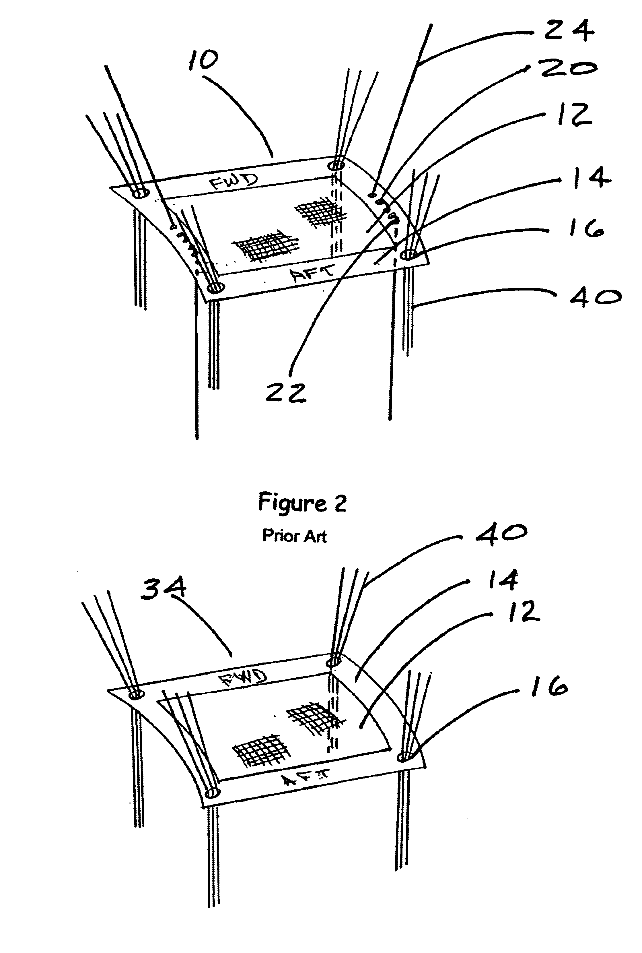
For extending the reefing process; if the components are properly designed and fabricated, there is no functional difference between the fully anchored configuration and the partially anchored configuration. However, the partially anchored configuration will have a dangling / trailing slider retardation cord and the fully anchored one will not. Very importantly, having a slider retardation cord that is anchored at both ends, preventing its escape from the restriction means during routine operation, will also avoid many packing and rigging complications during subsequent repacking that may cause parachute malfunctions. Furthermore, having a slider retardation cord that remains threaded through the retardation cord restriction
assembly, and is anchored at both ends, will decrease the amount of slider
flutter and the associated
noise.
Because the reefing slider design taught herein is not especially dependent on
aerodynamic drag to function properly, in some applications, the amount of fabric comprising the slider can be reduced, thereby reducing drag, and having less drag after a gliding parafoil type parachute is fully open is typically very desirable. Additionally, a
flagging and
flapping slider is quite noisy. Using a smaller amount of fabric in the slider configuration will, to some degree, reduce
flagging and
flapping, and, thereby the
noise, which can be extremely desirable for covert military operations. In some instances, the membranous fabric of the slider may be replaced with highly permeable mesh, or made of skeletal
webbing, which will produce even less drag and less
noise.

