

Improved ecg-based triggering for magnetic resonance imaging
a technology of magnetic resonance imaging and ecg, applied in the direction of magnetic measurement, instruments, measurement devices, etc., can solve problems such as synchronization, and achieve the effect of reducing the number of erroneous acquisition periods
- Summary
- Abstract
- Description
- Claims
- Application Information
AI Technical Summary
Benefits of technology
Problems solved by technology
Method used
Image

Examples
first embodiment
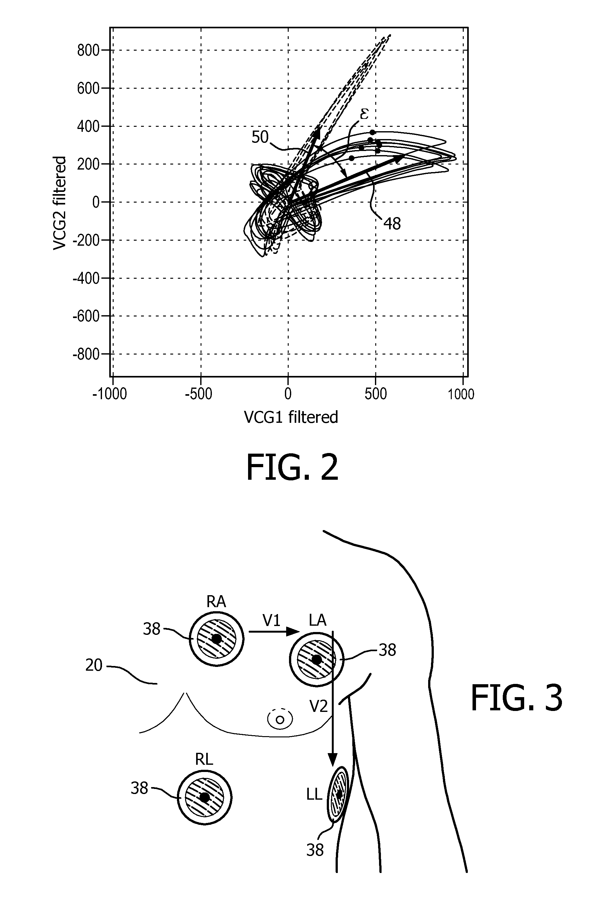
[0061]In the method, the step of adapting comprises modifying the angular relationship between the determined electrical axis of the heart and the instantaneous vector 50 of the vector cardiogram. The modifying of the angular relationship between the determined electrical axis of the heart and the instantaneous vector 50 of the vector cardiogram includes adjusting the angle ε formed by the electrical axis direction 48 of the determined electrical axis of the heart and the instantaneous vector 50 of the vector cardiogram by a predetermined amount in case of a transition between a subject's breathing status of full expiration to a subject's status of full inspiration.
[0062]In the first embodiment of the step of adapting, the predetermined amount is −40°; i.e. the angle ε in the vector cardiogram formed by the determined electrical axis of the heart and the instantaneous vector 50 of the vector cardiogram is reduced by 40°. Numerically, this can be accomplished by rotating the determin...
second embodiment
[0063]In the step of adapting, an angle ε formed by the determined electrical axis of the heart and an instantaneous vector 50 of a vector cardiogram is adjusted by an amount derived from an angular position of an instantaneous vector 50 of the vector cardiogram with respect to the determined electrical axis of the heart from an earlier-determined parameter of an acquisition period. In this embodiment, which requires a higher effort of data analysis, the shifting of the actual electrical axis of the heart can be tracked by and by, usually by tracking the R-peak of the QRS complex of the electrocardiogram, which results in an excellent synchronization of magnetic resonance images and a cyclic movement of the heart of the subject of interest 20. In the vector cardiogram of FIG. 5, the shifting of the actual electrical axis of the heart is reflected in continuously moving circular third trigger regions 561 to 56n, which are indicated by a number of circles for a number of corresponding...
third embodiment
[0064]In a third embodiment, the method further comprises, prior to determining a parameter of an acquisition period, a step of calibrating, wherein a predetermined amount for adjusting the angle ε formed by the determined electrical axis of the heart and the instantaneous vector 50 of the vector cardiogram, which can be used in the step of adapting the discriminating function after the calibrating, is individually determined for the subject of interest 20 from vector cardiogram data taken in the subject's breathing status of full expiration and the subject's status of full inspiration.
[0065]Table 1 shows experimental results for determining an actual electrical axis of the heart for various changes between an individual subject's breathing status of full expiration and the subject's status of full inspiration. Although the results show a subject-specific variance, an average of about 30° has been obtained, and can be used for adjusting the angle ε formed by the determined electrica...
PUM
 Abstract
Description
Claims
Application Information