Vehicle restraining device
- Summary
- Abstract
- Description
- Claims
- Application Information
AI Technical Summary
Benefits of technology
Problems solved by technology
Method used
Image

Examples
Example
First Embodiment
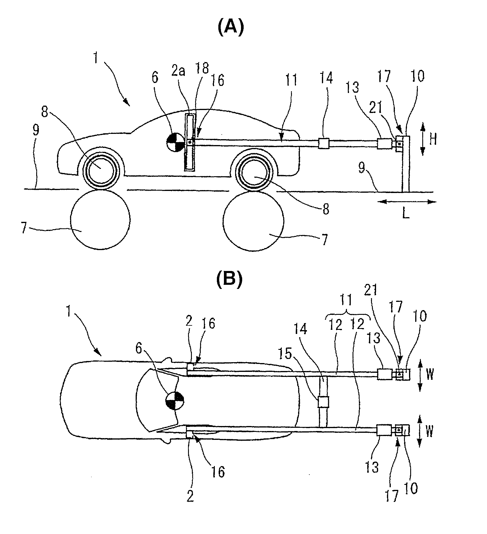
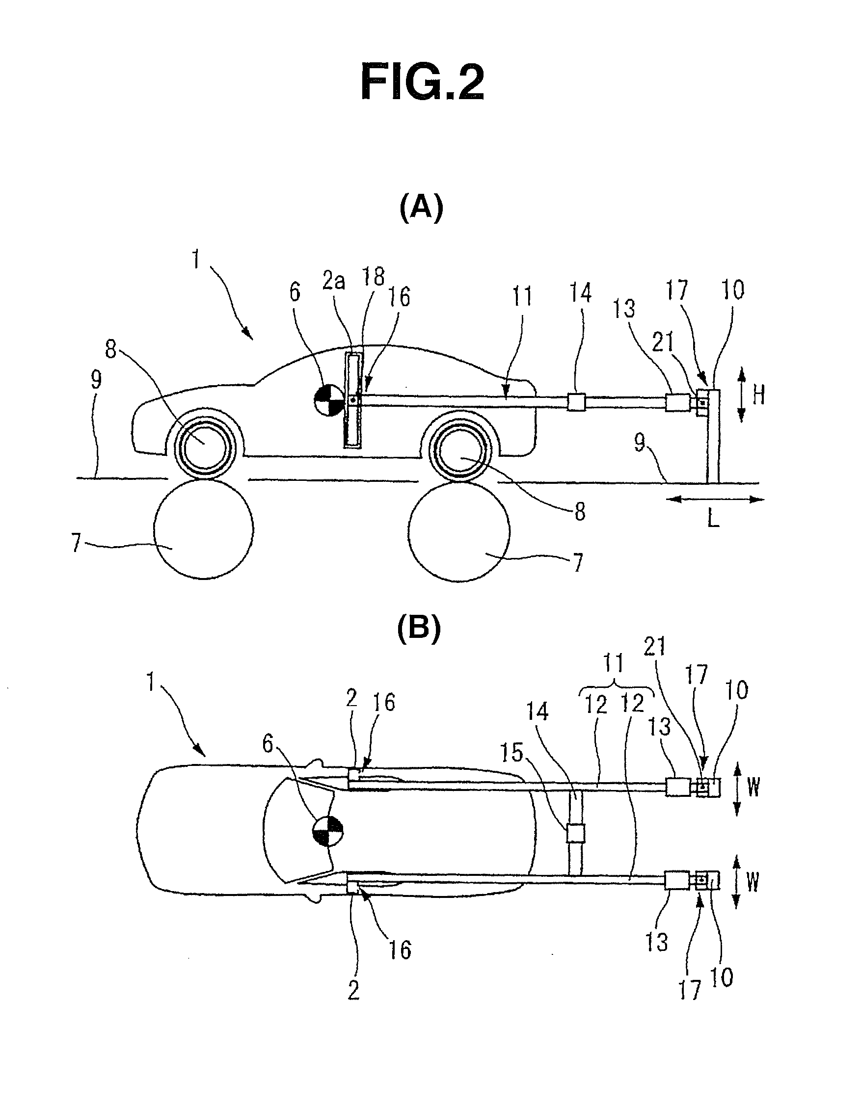
[0061]FIGS. 2(A) and 2(B) are schematic side view and schematic plan view of a vehicle 1 held by using a vehicle restraint apparatus or device 11 according to a first embodiment.
[0062]The vehicle restraint apparatus 11 includes a pair of vehicle restraining jigs or tools 12, 12 each of which includes a first end joined with one of the left and right seatbelt fixing pillars 2 of the vehicle 1 having tires 8 mounted on rollers 7 of a chassis dynamometer, and a second end joined with one of left and right poles 10 standing on a floor 9.
[0063]Vehicle restraining jigs 12, 12 are made of material having tensile strength and compression strength required for restraining longitudinal movement or forward / rearward movement of the vehicle, such as plate, sheet or pipe of steel or other material having a superior mechanical strength. Each of vehicle restraining jigs 12, 12 is provided with a length adjusting mechanism 13, such as a turnbuckle, capable of adjusting the length of ...
Example
Second Embodiment
[0079]FIG. 4 shows a second embodiment. In this embodiment, there is provided, between the second link mechanism 17 and poles 10 in the mode of the first embodiment, one or more restraining force sensors 29 which are arranged to sense a restraining force of the vehicle. The positions of restraining force sensors 29 are not limited to the region between second link mechanism 17 and poles 10. Restraining force sensors 29 may be provided at positions between vehicle restraining jigs 12 and second link mechanism 17, positions between first link mechanism 16 and seatbelt fixing pillars 2, or some other positions capable of securely sensing the restraining force of restraining vehicle 1. The vehicle restraint apparatus 11 of this embodiment capable of sensing the vehicle restraining force makes it possible to measure, analyze and evaluate the vehicle sprung characteristics, in addition to the effects of the first embodiment.
Example
Third Embodiment
[0080]FIGS. 5˜9 show a third embodiment. In this embodiment, as shown in FIG. 5, a first link mechanism 31 joining the first ends of vehicle restraining jigs 12 rotatably with the seatbelt fixing pillars 2 includes tubular shaft portions 32 to which the first ends of vehicle restraining jigs 12 are, respectively, attached rotatably, and shaft supporting arms 33 attaching the shaft portions 32 to the seatbelt fixing pillars 2, respectively.
[0081]As shown in FIGS. 6˜8, the shaft supporting arms 33 are T-shaped members shaped like a letter T. The shaft portion 32 is provided in a second end of each shaft supporting arm 33, and a first end portion of shaft supporting arm 33 is fastened to the seatbelt fixing pillar 2 by screw fasteners 34. The height position of each shaft supporting arm 33 is adjustable by selecting some of screw holes 35 formed in the seatbelt fixing pillar 2.
[0082]Shaft supporting arm 33 is T-shaped to shift the position of shaft portion 32 in the fro...
PUM
 Abstract
Description
Claims
Application Information
 - R&D Engineer
- R&D Manager
- IP Professional
- Industry Leading Data Capabilities
- Powerful AI technology
- Patent DNA Extraction
Browse by: Latest US Patents, China's latest patents, Technical Efficacy Thesaurus, Application Domain, Technology Topic.
© 2024 PatSnap. All rights reserved.Legal|Privacy policy|Modern Slavery Act Transparency Statement|Sitemap