Optical switch keyboard

Inactive Publication Date: 2017-06-15
PRIMAX ELECTRONICS LTD
View PDF3 Cites 8 Cited by
  • Summary
  • Abstract
  • Description
  • Claims
  • Application Information

AI Technical Summary

Benefits of technology

[0005]The present invention provides an optical switch keyboard. A key is disposed over the circuit board. A light emitter and a light receiver for generating a conducting signal are disposed under

Problems solved by technology

However, the conventional optical switch 9 still has some drawbacks.
Under this circumstan

Method used


Image

  • Optical switch keyboard
  • Optical switch keyboard
  • Optical switch keyboard

Examples


Embodiment Construction

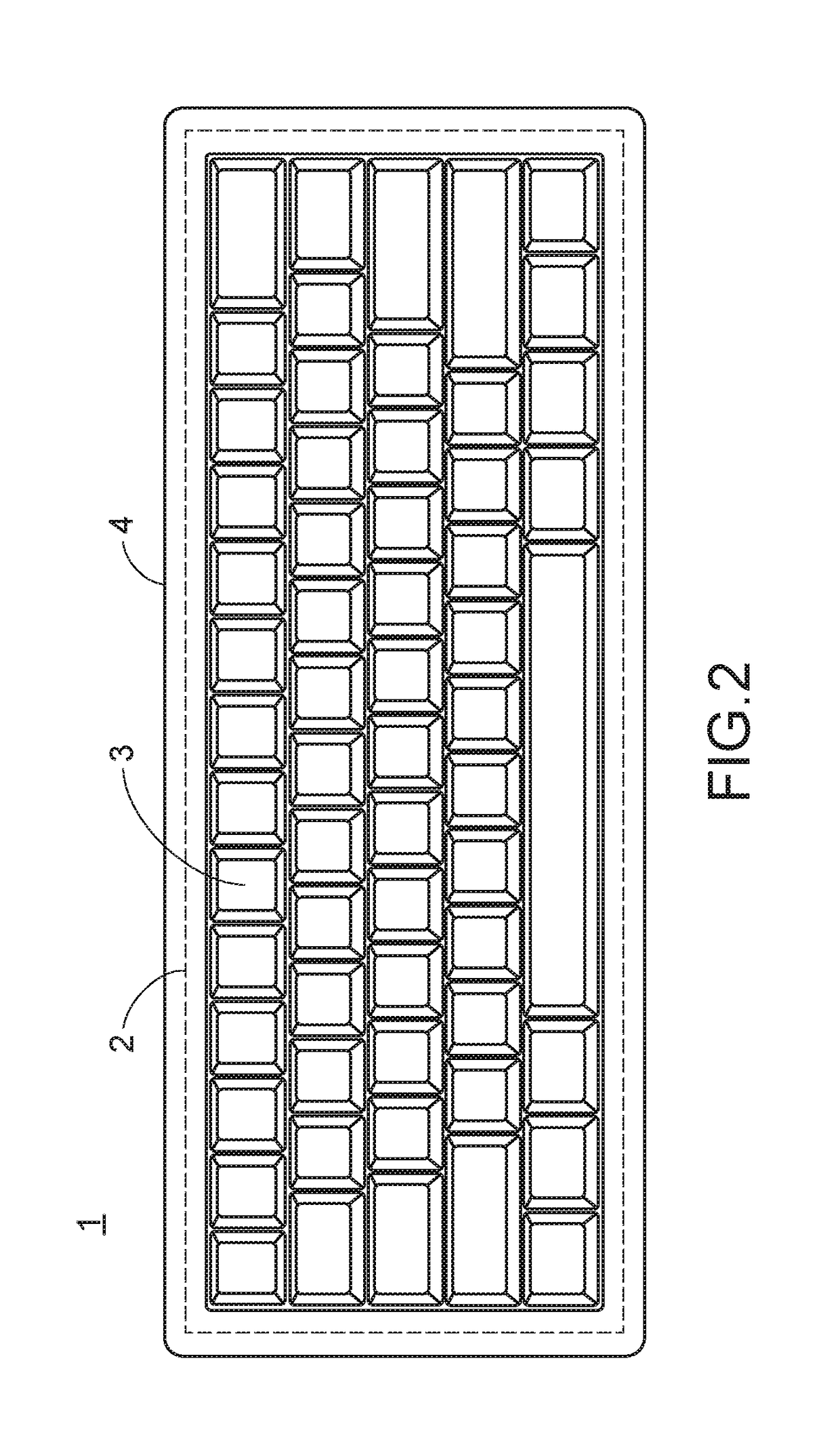
[0026]FIG. 2 is a schematic top view illustrating an optical switch keyboard according to an embodiment of the present invention. As shown in FIG. 2, the optical switch keyboard 1 comprises a circuit module 2, plural keys 3 and an outer shell 4. The plural keys 3 are disposed on the circuit module 2. Moreover, plural optical switches are defined by the plural keys 3 and the circuit module 2 collaboratively. The periphery of the circuit module 2 is covered by the outer shell 4, and the plural keys 3 are enclosed by the outer shell 4. Consequently, the outer appearance of the optical switch keyboard is constructed.

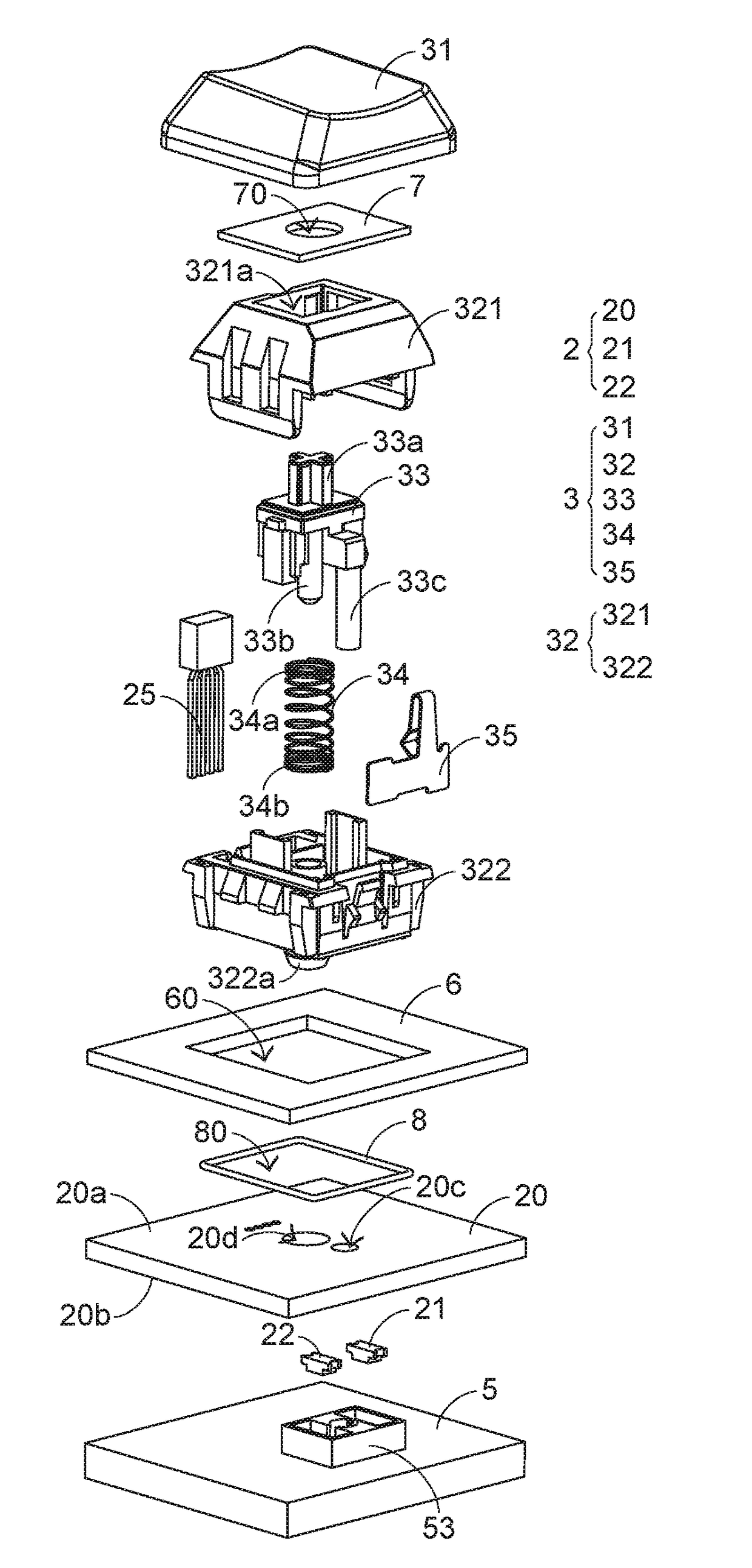
[0027]For succinctness, only a single optical switch is shown in FIGS. 3 and 4. FIG. 3 is a schematic perspective view illustrating a single optical switch of the optical switch keyboard according to a first embodiment of the present invention. FIG. 4 is a schematic exploded view illustrating the optical switch of the optical switch keyboard according to the first embodiment...


PUM


Abstract

An optical switch keyboard includes a circuit module and plural keys. The plural keys are disposed over the circuit module. The circuit module includes a circuit board, plural light emitters and plural light receivers. Each key is disposed on a top surface of the circuit board. Each key corresponds to a light emitter and a light receiver. The plural light emitters and the plural light receivers are disposed on a bottom surface of the circuit board. Consequently, the plural light emitters and the plural light receivers are not interfered by the ambient light that comes from the top side of the circuit board. In addition, the optical switch keyboard has waterproof structures to prevent foreign liquid from entering the optical switch keyboard.

Description

FIELD OF THE INVENTION[0001]The present invention relates to a keyboard, and more particularly to a keyboard with optical switches.BACKGROUND OF THE INVENTION[0002]A keyboard is an essential input device of a computer system. The keyboard is equipped with many keys. By depressing a key of the keyboard, a command is inputted into the computer system. Conventionally, many kinds of keys are designed to generate key signals. For example, a mechanical key uses a conductive pin to trigger a circuit switch to generate a key signal. In addition, an optical key generates a key signal according to the result of receiving or obstructing a sensing light.[0003]FIG. 1 is a schematic view illustrating the structure of a conventional optical switch 9. As shown in FIG. 1, a key part 84 is disposed over a circuit board 83 for being pressed by a user. A light emitter 81 and a light receiver 82 for generating a conducting signal are opposed to each other. Moreover, the light emitter 81 and the light re...

Claims


Application Information

Patent Timeline
IPC IPC(8): H01H13/83H01H13/06
CPCH01H13/83H01H2219/054H01H13/06H03K17/9629H01H2215/03H01H2223/002H03K17/968H03K17/943
Inventor CHEN, BO-ANLIU, CHIEN-HUNG
Owner PRIMAX ELECTRONICS LTD
Why Eureka
Try Eureka