Method for improving color rendition in a head-worn computer

Inactive Publication Date: 2017-08-24
OSTERHOUT GROUP INC
View PDF4 Cites 42 Cited by
  • Summary
  • Abstract
  • Description
  • Claims
  • Application Information

AI Technical Summary

Benefits of technology

[0008]In an aspect, a head-worn computer with improved color rendition may include an image source with an array of pixels, comprising subpixels, emitting a white light associated with digital content of a displayed image and a color filter array, wherein a color filter is associated with each subpixel to provide a colored image light from each subpixel and a lens for displaying an image within a field of view, comprising colored image light from the subpixels, to a user using the head-worn computer, wherein the lens samples the colored image light from each subpixel to provide the displayed image to the user, wherein a chief ray angle is associated with the light emitted by each subpixel as sampled by the lens. The color filters may be shifted relative to the associated subpixels in correspondence to the chief ray angles. The color filters may be shifted in correspondence to a distance from the center of the image source to the position of each subpixel. Each pixel includes at least three subpixels. The color filters associated with the at least three subpixels include red, green and blue color filters. The color filters associated with the at least three subpixels include cyan, magenta and yellow color filters. Each pixel includes at least four subpixels and the color filters associated with the at least four subpixels include a white color filter. A maximum chief ray angle may be greater than 25 degrees. A maximum chief ray angle may be greater than 40 degrees. The displayed image may be provided to the user with a field of view greater than 30 degrees. The displayed image may be provided to the user with a field of view greater than 50 degrees. The head-worn computer may provide a wide display field of view. The head-worn computer further includes a transparent layer with a thickness between the subpixels and the color filter array. The color filters may be shifted in correspondence to a distance from the center of the image source to the position of each subpixel and the thickness of the transparent layer. The color filters may be shifted in correspondence to a distance from the center of the image source to the position of each subpixel, the thickness of the transparent layer and the chief ray angle associated with each subpixel. The chief ray angle associated with each subpixel may be in correspondence to the focal length of the lens and the display field of view. The color filters may be progressively outwardly shifted relative to the subpixels so that the color filter array has an increased area compared to an area of the pixel array. The distance may be radially based with a progressive radial shift of the color filters. The distance may be linearly based with a progressive X direction shift. The distance may be rectilinearly based with a progressive X direction and Y direction shift.
[0009]In an aspect, a head-worn computer with improved color rendition may include an image source with pixels, comprised of subpixels, emitting a white light associated with digital content of a displayed image and a color filter array wherein a color filter is positioned above each subpixel to provide a colored image light from each subpixel, a lens for displaying an image within a field of view, comprising colored image light from the subpixels, to a user using the head-worn computer, wherein the lens samples the colored image light from each of the subpixels to provide the displayed image to the user, wherein a chief ray angle is associated with the colored light as sampled by the lens, and an optical film positioned on top of the color filter array that repoints the

Problems solved by technology

The presentation of content in the see-through display can be a complicated

Method used


Image

  • Method for improving color rendition in a head-worn computer
  • Method for improving color rendition in a head-worn computer
  • Method for improving color rendition in a head-worn computer

Examples


Example

[0055]While the disclosure has been described in connection with certain preferred embodiments, other embodiments would be understood by one of ordinary skill in the art and are encompassed herein.

DETAILED DESCRIPTION OF THE PREFERRED EMBODIMENT(S)

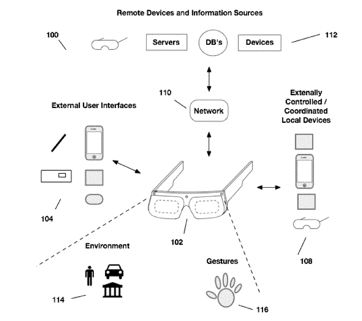
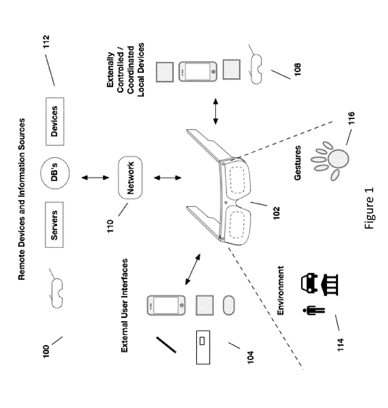
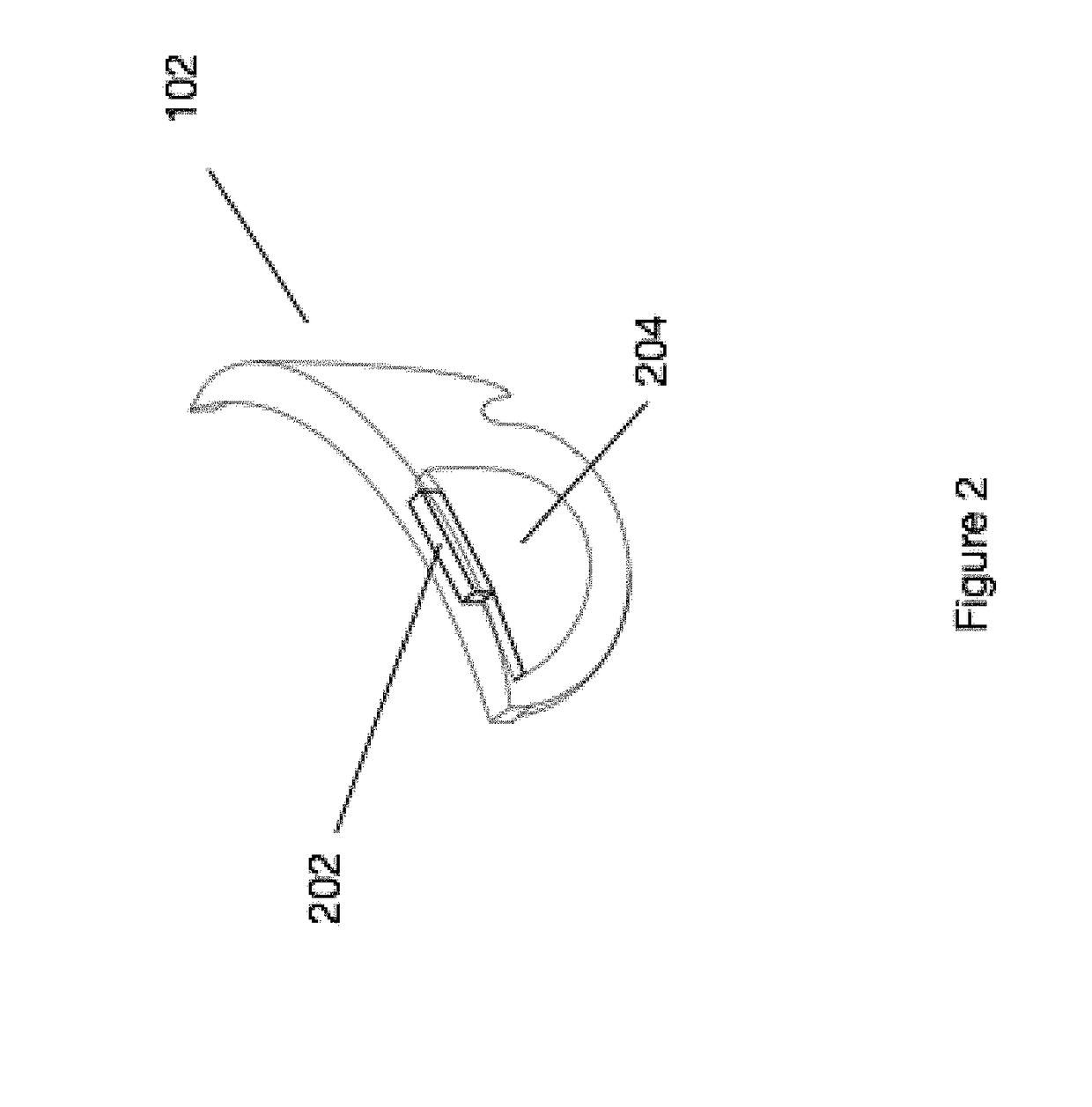
[0056]Aspects of the present disclosure relate to head-worn computing (“HWC”) systems. HWC involves, in some instances, a system that mimics the appearance of head-worn glasses or sunglasses. The glasses may be a fully developed computing platform, such as including computer displays presented in each of the lenses of the glasses to the eyes of the user. In embodiments, the lenses and displays may be configured to allow a person wearing the glasses to see the environment through the lenses while also seeing, simultaneously, digital imagery, which forms an overlaid image that is perceived by the person as a digitally augmented image of the environment, or augmented reality (“AR”).

[0057]HWC involves more than just placing a computing system ...


PUM


Abstract

Aspects of the present disclosure relate to a method for improving color rendition in images displayed to a user of a head-worn computer as digital images with colored subpixels, the method including determining the colors associated with each color filter in the color filter array, determining the subpixels positioned under each color filter in the color filter array along the chief ray angles sampled by the lens, shifting the digital code values between subpixels in the digital image to provide a modified digital image, wherein digital code values within the modified image are positioned at the determined subpixels positioned under each color filter along the chief ray angles sampled by the lens in correspondence to the colored subpixels in the digital image, and displaying the modified digital image in the head-worn computer.

Description

CROSS REFERENCE OF RELATED APPLICATIONS[0001]This application claims the benefit of priority to and is a continuation of the following U.S. patent application, which is incorporated by reference herein in its entirety:[0002]U.S. non-provisional application Ser. No. 15 / 051,365, filed Feb. 23, 2016 (ODGP-2024-U01).BACKGROUND[0003]Field of the Invention[0004]This disclosure relates to optical systems for head-worn computer systems.[0005]Description of Related Art[0006]Head mounted displays (HMDs) and particularly HMDs that provide a see-through view of the environment are valuable instruments. The presentation of content in the see-through display can be a complicated operation when attempting to ensure that the user experience is optimized. Improved systems and methods for presenting content in the see-through display are required to improve the user experience.SUMMARY[0007]Aspects of the present disclosure relate to methods and systems for providing optical systems in head-worn compu...

Claims


Application Information

Patent Timeline
IPC IPC(8): G09G5/02G02B27/01
CPCG09G5/02G02B2027/014G02B2027/0178G02B27/017G02B27/0176G02B5/201G02B27/0093G02B27/0172G02B2027/0112G02B2027/012G02B2027/0123G02B2027/0156G02B2027/0174G06F3/147G09G2320/0261
Inventor BORDER, JOHN N.HADDICK, JOHN D.
Owner OSTERHOUT GROUP INC
Why Eureka
Try Eureka