Refrigerant supply device, cooling device, and cooling system

a cooling device and refrigerant supply technology, applied in indirect heat exchangers, lighting and heating devices, instruments, etc., can solve the problems of ambient temperature rising, high-performance electronic devices consuming a large amount of electric power, and most of the electric power consumption of electronic devices is converted into heat, and achieves a small lateral width

Active Publication Date: 2017-10-26
NEC PLATFORMS LTD
View PDF3 Cites 0 Cited by
  • Summary
  • Abstract
  • Description
  • Claims
  • Application Information

AI Technical Summary

Benefits of technology

[0013]The present invention has effects of providing a refrigerant supply device with a small lateral width and a capacity to supply refrigerant evenly among heat receivers disposed in multiple tiers.

Problems solved by technology

Generally, high-performance electronic devices consume a large amount of electric power.
And most of the electric power consumption of the electronic devices is converted into heat.
Therefore, installing high-performance electronic devices cause ambient temperature rising due to their exhaust heat consequently.
Particularly, in data centers having many electronic devices such as servers, the electronic devices emit a large amount of heat.
In such a case, the electronic devices need to be cooled to maintain their functions, thus the air conditioning system requires a large amount of electric power.

Method used


Image

  • Refrigerant supply device, cooling device, and cooling system
  • Refrigerant supply device, cooling device, and cooling system
  • Refrigerant supply device, cooling device, and cooling system

Examples


first example embodiment

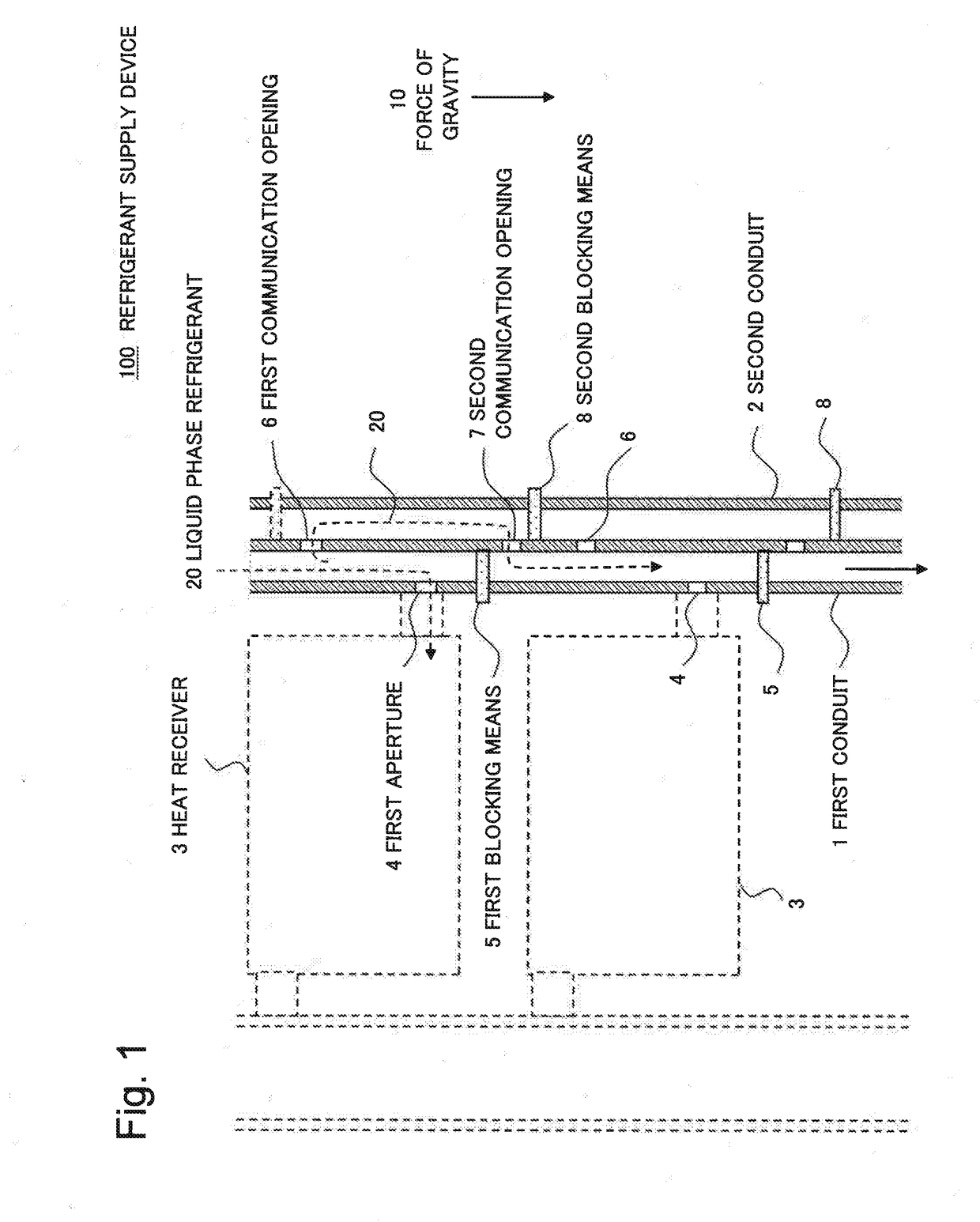
[0024]FIG. 1 is a cross-sectional view illustrating a first example embodiment. The present example embodiment is a refrigerant supply device for distributing, by force of gravity 10, liquid phase refrigerant to heat receivers disposed in a plurality of tiers. A refrigerant supply device according to the present example embodiment 100 includes a first conduit 1 for supplying refrigerant to heat receivers, and a second conduit 2 provided in parallel with the first conduit 1 and sharing part of its conduit wall with the first conduit 1. The first conduit 1 includes a first aperture 4 through which the refrigerant flows to a heat receiver 3 and a first blocking means 5 provided below the first aperture 4 for blocking the first conduit 1. The refrigerant supply device 100 also includes a first communication opening 6 provided above the first aperture 4 and communicating the first conduit 1 and the second conduit 2. The refrigerant supply device 100 also includes a second communication o...

second example embodiment

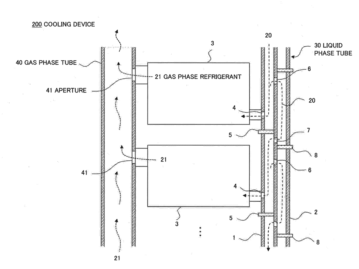
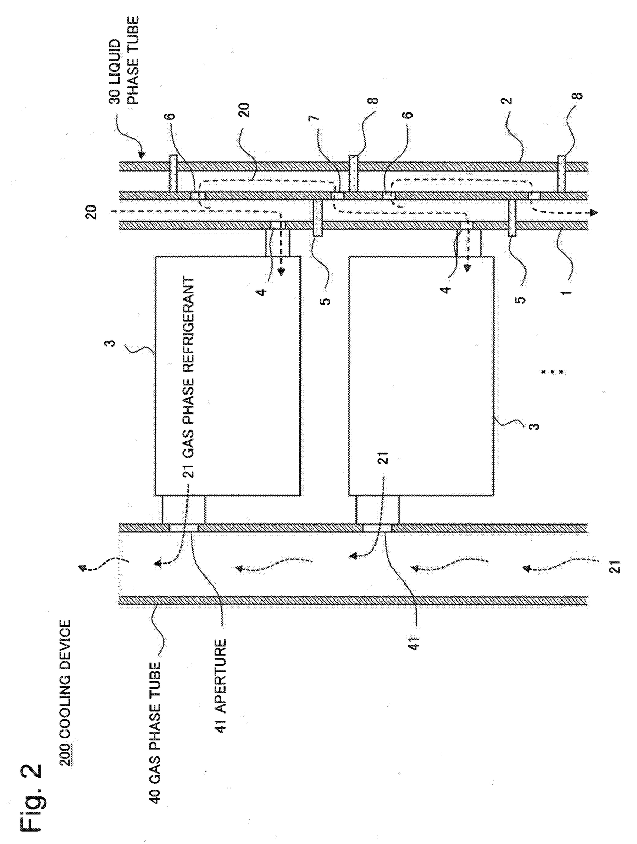
[0027]FIG. 2 is a cross-sectional view illustrating a present example embodiment. The present example embodiment is a cooling device equipped with the refrigerant supply device 100 of the first example embodiment. Herein, the refrigerant supply device 100 is also referred to as liquid phase tube 30 for the sake of simplicity and in light of its function in the cooling device 200.

[0028]The cooling device 200 includes a liquid phase tube 30, heat receivers 3 disposed in a plurality of tiers, and a gas phase tube 40. The gas phase tube 40 is provided with apertures 41 at positions corresponding to respective heat exhaust ports of the heat receivers 3, and connected with the heat receivers 3. Note that the heat receivers 3 used in the present example embodiment is an application of so-called ebullient cooling system, that is, heat is absorbed when the liquid phase refrigerant 20 boils in the heat receivers 3. The heat receivers 3 need only to be suitable to the ebullient cooling system,...

third example embodiment

[0032]FIG. 3 is a cross-sectional view illustrating a third example embodiment. The present example embodiment provides a configuration example of the cooling device 200 applied to a heat receiver 3 on the lowest tier. At the end 30a of the liquid phase tube 30 on the lowest tier, the first conduit 1 and the second conduit 2 are both blocked. The end 40a of the gas phase tube 40 is also blocked. It is not necessary to provide a first communication opening 6 at the lowest tier of the liquid phase tube 30 because the liquid phase refrigerant 20 need not be supplied further downward.

[0033]The lowest tier of the liquid phase tube 30 supplies the liquid phase refrigerant 20 to the heat receiver 3 of the lowest tier, and the lowest tier of the gas phase tube 40 receives the gas phase refrigerant from the heat receiver 3 of the lowest tier. Together with the radiator not shown, a closed circuit cooling system is thus formed.

[0034]As described above, the present example embodiment enables a...


PUM


Abstract

[Problem]
A refrigerant supply device with a small lateral width and a capacity to supply refrigerant evenly among heat receivers disposed in multiple tiers needs to be provided.
[Solution]
A refrigerant supply device for distributing, by force of gravity, liquid phase refrigerant to heat receivers disposed in a plurality of tiers includes: a first conduit for supplying the refrigerant to the heat receivers; a second conduit provided in parallel with the first conduit; a first aperture provided in the first conduit for supplying the refrigerant to one of the heat receivers; a first blocking means provided below the first aperture for blocking the first conduit; a first communication opening provided above the first aperture and communicating the first conduit and the second conduit; a second communication opening provided below the first blocking means and communicating the first conduit and the second conduit; and a second blocking means provided below the second communication opening for blocking the second conduit.

Description

TECHNICAL FIELD[0001]The present invention relates to a refrigerant supply device, a cooling device, and a cooling system.BACKGROUND ART[0002]With the development of information society in recent years, the amount of data is expected to increase greatly. To respond to the expected increase in the amount of data, it is necessary to install many high-performance servers and other electronic devices. Generally, high-performance electronic devices consume a large amount of electric power. And most of the electric power consumption of the electronic devices is converted into heat. Therefore, installing high-performance electronic devices cause ambient temperature rising due to their exhaust heat consequently. Particularly, in data centers having many electronic devices such as servers, the electronic devices emit a large amount of heat. In such a case, the electronic devices need to be cooled to maintain their functions, thus the air conditioning system requires a large amount of electri...

Claims


Application Information

Patent Timeline
Patent Type & Authority Applications(United States)
IPC IPC(8): H05K7/20F28F9/02
CPCH05K7/20818H05K7/20327F28F9/0204F28D15/02G06F1/20H05K7/20F25B23/006
Inventor HOSAKA, TADAO
Owner NEC PLATFORMS LTD
Why Eureka
Try Eureka