Single photon avalanche diode

a single-photon, avalanche technology, applied in the direction of diodes, semiconductor devices, radiation controlled devices, etc., can solve the problems of reducing the aperture ratio of the spad array compared to the two-dimensional array structure, the difficulty of forming the high electric field area, and the performance of low time resolution will deteriorate, so as to reduce the distance between neighboring spads and reduce the lateral width of the depletion layer , the effect of increasing the aperture ratio

Active Publication Date: 2015-02-26
TOYOTA CENT RES & DEV LAB INC
View PDF0 Cites 117 Cited by
  • Summary
  • Abstract
  • Description
  • Claims
  • Application Information

AI Technical Summary

Benefits of technology

[0019]According to an aspect of the present invention, a single photon avalanche photodiode (SPAD) includes a first semiconductor layer of a first conductivity type, a second semiconductor layer of a second conductivity type provided under the first semiconductor layer, in which the second conductivity type is opposite to the first conductivity type, and a third semiconductor layer of the second conductivity type, which surrounds the first semiconductor layer. The SPAD further includes an epitaxial layer of the second conductivity type, which is formed on a substrate, a first contact connected to the first semiconductor layer via a conducting layer of the first conductivity type, and a second contact connected to the second semiconductor layer via a conducting layer of the second conductivity type. The second semiconductor layer is buried in the epitaxial layer. The second semiconductor layer can be completely depleted of carriers when an appropriate bias voltage is applied between the first contact and the second contact. Therefore, the junction between the first semiconductor layer and the second semiconductor layer forms a planar avalanche multiplication area that is substantially parallel to the surface of the substrate. The lateral width of the depletion layer between the first semiconductor layer and the third semiconductor layer becomes smaller than the vertical width of the depletion layer between the first semiconductor layer and the epitaxial layer. Because the lateral width of the depletion layer is small, the distance between neighboring SPADs can be reduced, and the aperture ratio can be increased. The photon detection efficiency can be increased because the width of the depletion layer in the depth direction is large.

Problems solved by technology

However, the aperture ratio of a SPAD array is small compared to that of a two-dimensional array structure of a conventional diode.
A major challenge in designing the SPAD is the difficulty of forming the high electric field area (more specifically, the avalanche multiplication area) having a highly uniform planar structure under severe variability of the employed semiconductor manufacturing process.
Such a low time resolution will deteriorate performance when high time resolution is required in the application (e.g., TOF).
The sensitivity of the conventional SPAD is dissatisfactory in the near infrared region.
However, the above-mentioned technique is defective in the following two points.
First, the crystal defect density is high at the interface region between the silicon and the STI.
Therefore, the STI / silicon interface tends to cause false counts, i.e. dark counts.
However, the buried layer having the above-mentioned structure cannot be realized by the CMOS process.
However, the use of the microlens array is not effective in many low-light applications, because those applications require an optical system having a small F-number.
Therefore, manufacturing costs increase.
Therefore, realizing such a large and thick microlens further increases manufacturing costs.

Method used


Image

  • Single photon avalanche diode
  • Single photon avalanche diode
  • Single photon avalanche diode

Examples


first embodiment

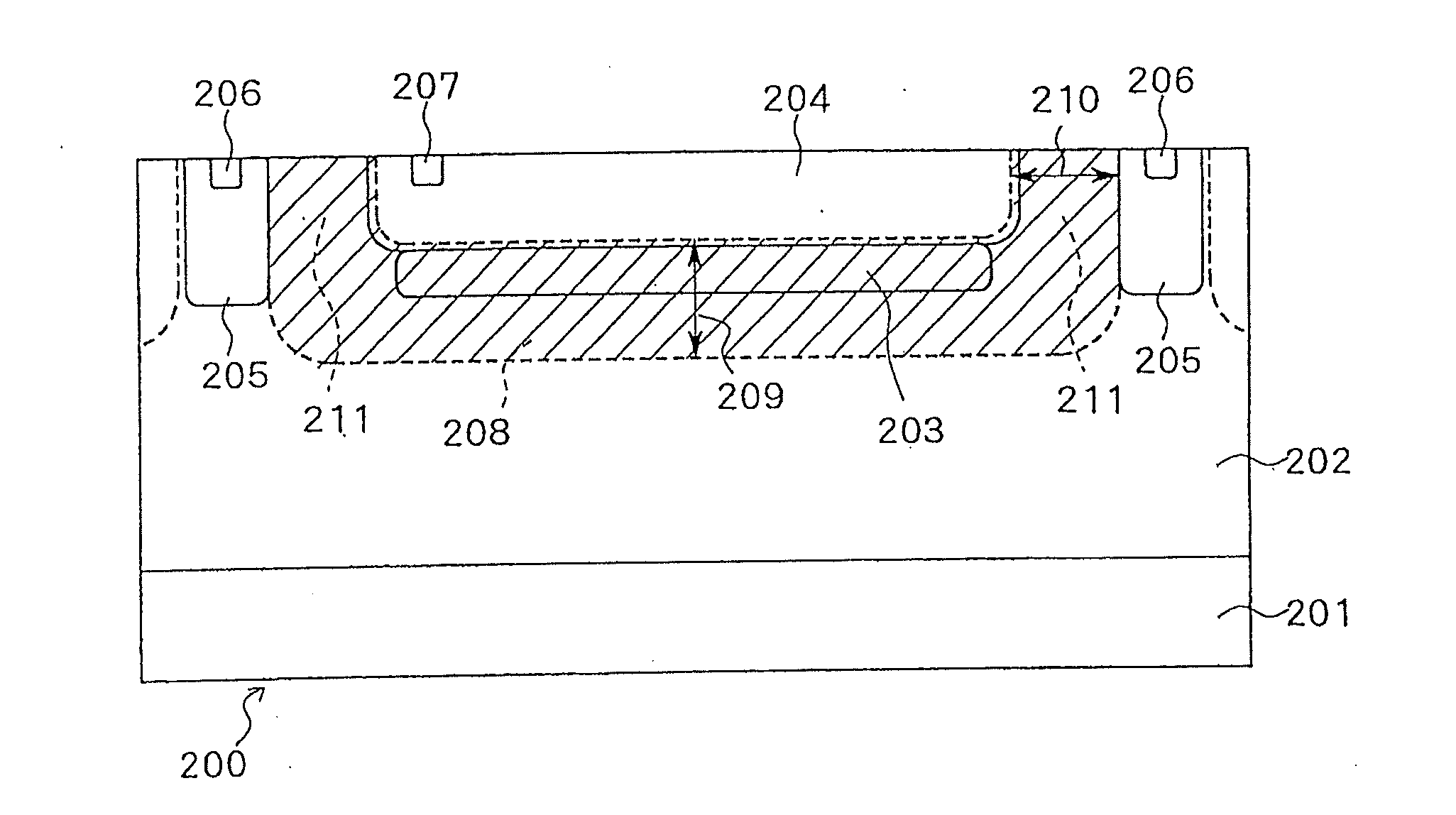
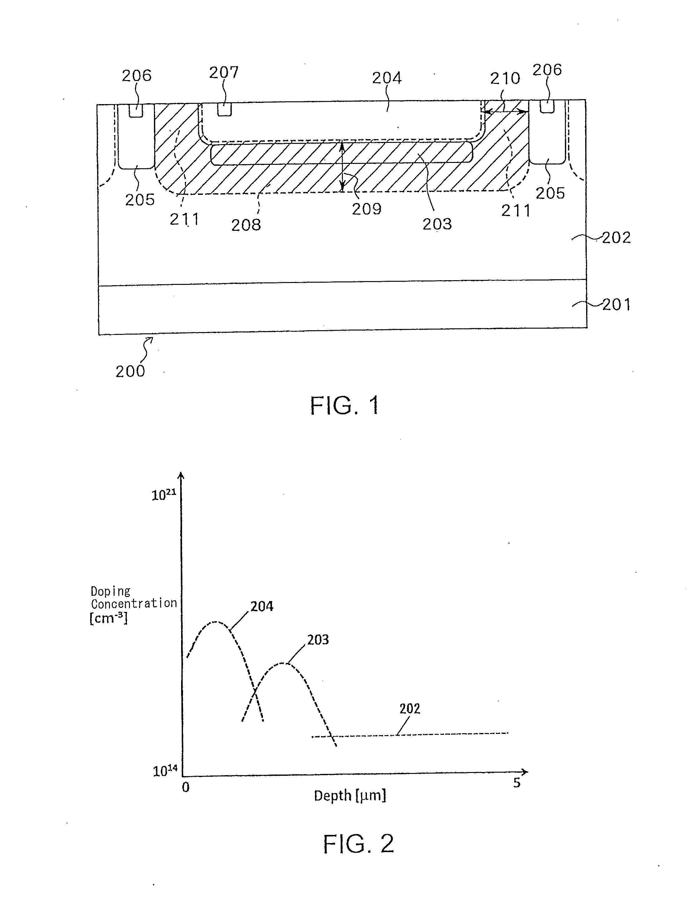
[0032]FIG. 1 is a cross-sectional view illustrating a SPAD according to a first embodiment of the present invention. The SPAD according to the present embodiment includes a second semiconductor layer 203 that is buried within an epitaxial layer 202 and of the same conductivity type as the epitaxial layer 202. Further, the SPAD illustrated in FIG. 1 includes a first semiconductor layer 204 that is implanted above the second semiconductor layer 203 and is of the opposite conductivity type to the epitaxial layer 202. The epitaxial layer 202 is a layer that has grown on a silicon substrate 201. The silicon substrate 201 is of the same type as the epitaxial layer 202. It is preferred that the second semiconductor layer 203, the epitaxial layer 202, and the silicon substrate 201 be of p-type conductivity. On the other hand, it is preferred that the first semiconductor layer 204 be of n-type conductivity. The SPAD formed by the first semiconductor layer 204 and the second semiconductor lay...

second embodiment

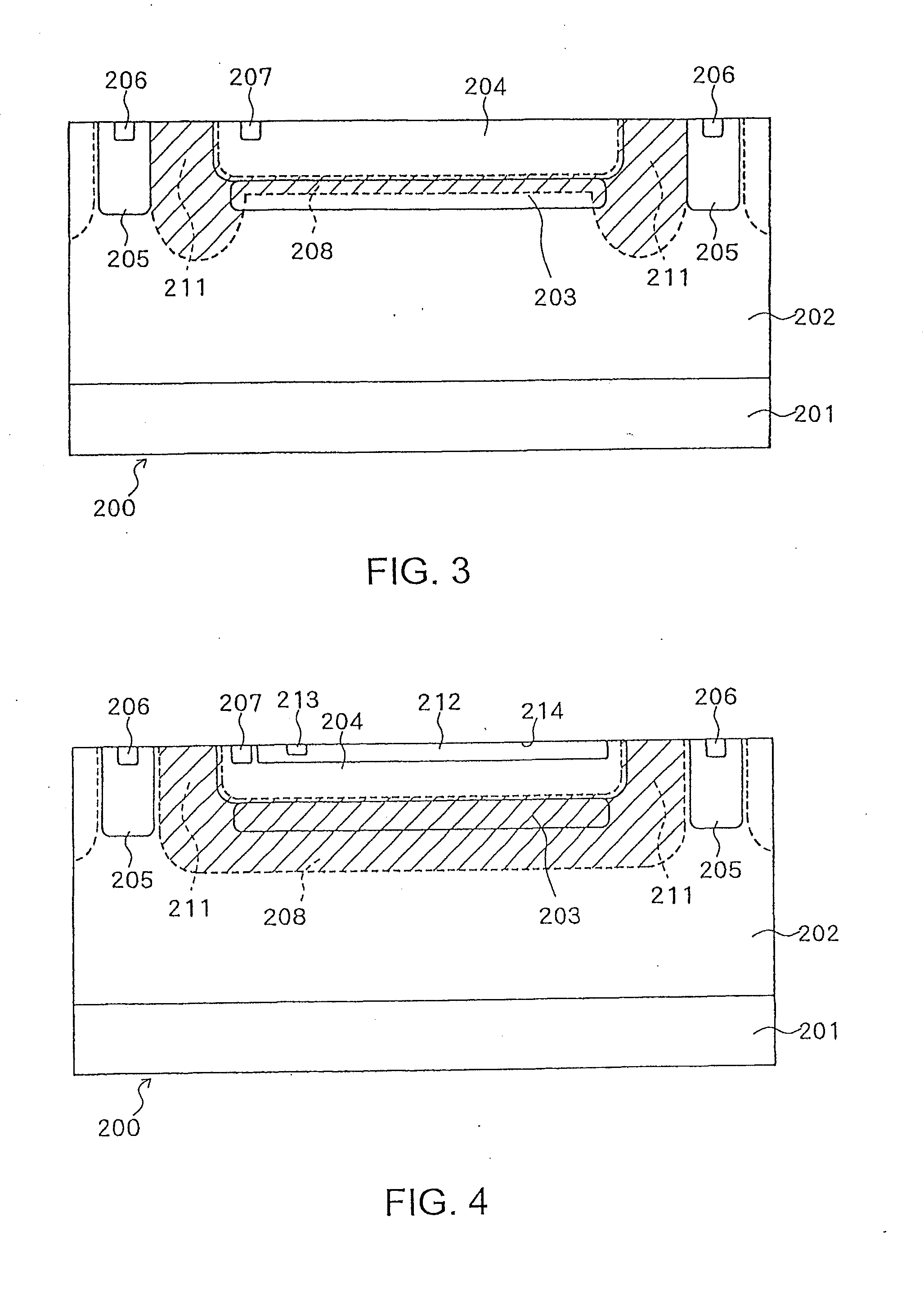
[0042]FIG. 4 illustrates a SPAD configuration according to a second embodiment of the present invention. According to the SPAD configuration illustrated in FIG. 4, all of the second semiconductor layer 203, the third semiconductor layer 205, the epitaxial layer 202, and the substrate 201 are of p-type conductivity and the first semiconductor layer 204 is of n-type conductivity. In the present embodiment, a fourth semiconductor layer 212 is formed within the first semiconductor layer 204 of the SPAD. The fourth semiconductor layer 212 is shallow in shape and is of p-type conductivity. The fourth semiconductor layer 212 is formed in such a way as to sufficiently overlap the avalanche multiplication area formed between the first semiconductor layer 204 and the second semiconductor layer 203. At least one electrode 213 may be provided to connect the fourth semiconductor layer 212.

[0043]FIG. 5 illustrates an example of the doping profile of the SPAD according to the present embodiment. A...

third embodiment

[0047]FIG. 6 illustrates a SPAD configuration according to a third embodiment of the present invention. The SPAD illustrated in FIG. 6 is characteristically similar to the SPADs described in the above-mentioned embodiments.

[0048]In the present embodiment, the isolation of neighboring SPADs is implemented by a combination of the third semiconductor layer 205 and a buried isolation layer 215, instead of using only the third semiconductor layer 205. The third semiconductor layer 205 and the buried isolation layer 215 are of the same conductivity type and are stacked in the vertical direction. It is desired that the third semiconductor layer 205 and the buried isolation layer 215 are of p-type conductivity. The vertically stacked layers 205 and 215 can effectively prevent the depletion layer 208 of one SPAD from contacting the depletion layer 208 of a neighboring SPAD. In other words, the SPAD illustrated in FIG. 6 can improve the isolation between neighboring SPADs.

[0049]Layers usable ...


PUM


Abstract

A first semiconductor layer serves as a first implanted layer of a first conductivity type. A second semiconductor layer of a second conductivity type is provided under the first semiconductor layer. The second conductivity type is opposite to the first conductivity type. The second semiconductor layer is buried in an epitaxial layer grown above a substrate. The second semiconductor layer becomes fully depleted when an appropriate bias voltage is applied to the device.

Description

PRIORITY INFORMATION[0001]This application claims priority to Japanese Patent Application No. 2013-173592, filed on Aug. 23, 2013, which is incorporated herein by reference in its entirety.BACKGROUND OF THE INVENTION[0002]1. Field of the Invention[0003]The present invention relates to a single photon avalanche diode.[0004]2. Description of the Related Art[0005]An avalanche photodiode can be operated differently according to a selected mode. When the selected mode is Geiger mode, the avalanche photodiode operates under a reverse bias voltage higher than its breakdown voltage. When the selected mode is linear mode, the avalanche photodiode operates under a reverse bias voltage lower than the breakdown voltage. The avalanche photodiode operating in the Geiger mode is referred to as a single photon avalanche diode (SPAD), which is superior in some characteristics to the avalanche photodiode operating in the linear mode. The SPAD is capable of generating an electric signal in response to...

Claims


Application Information

Patent Timeline
Patent Type & Authority Applications(United States)
IPC IPC(8): H01L31/107H01L27/146
CPCH01L27/14643H01L31/107H01L27/1446
Inventor NICLASS, CRISTIANOSOGA, MINEKI
Owner TOYOTA CENT RES & DEV LAB INC
Why Eureka
Try Eureka