Guide for flexible transmission member

a technology of flexible transmission and guide, which is applied in the direction of belt/chain/gearing, mechanical equipment, belts, etc., can solve the problems of poor guide assembling efficiency, increased cost, and largely manual assembling, so as to prevent shoe elevation prevent shoe looseness, and increase the mating force

Inactive Publication Date: 2014-11-27
TSUBAKIMOTO CHAIN CO
View PDF0 Cites 4 Cited by
  • Summary
  • Abstract
  • Description
  • Claims
  • Application Information

AI Technical Summary

Benefits of technology

[0027]According to the configuration set forth in claim 5, the pair of lateral rims of the base include notches recessed downwards, each notch being formed by stepped portions in the height direction and a bottom part continuous with the stepped portions and extending in the longitudinal direction. The bottom part is the base-side lateral mating element. The second mating portion that meshes with the base-side lateral mating element at a position higher than the first mating portion is located inside the notch. As a result, since the notches are each formed by the stepping portions in the height direction and the bottom part is the base-side lateral mating element, the second mating portion positioned higher than the first mating portion in the shoe-side lateral mating element is located inside the notch. Consequently, the shoe-side lateral mating element protrudes less by the length of the stepping portions, or does not protrude at all, upward relative to the base-side lateral mating element, so that the guide can be made smaller in the height direction. The lateral rims of the base are made more lightweight by formation of the notches, and the shoe-side lateral mating elements are made smaller in the height direction, so that the base and shoe are made more lightweight.
[0028]According to the configuration set forth in claim 6, the base-side lateral mating part is formed by one or more first base-side lateral mating elements and second base-side lateral mating elements that are the base-side lateral mating elements. The shoe-side lateral mating part is formed by first shoe-side lateral mating elements as the elastic mating elements in a same number as the first base-side lateral mating elements, and second shoe-side lateral mating elements that are the shoe-side lateral mating elements. The first shoe-side lateral mating element each meshes with the first base-side lateral mating element in the height direction from an inner side in the width direction, and abuts on the first base-side lateral mating element from below in the meshed state to increase the mating force on the first base-side lateral mating element when the base and the shoe expand thermally. The first mating portion meshes with the second base-side lateral mating element in the height direction from an outer side in the width direction. The first shoe-side lateral mating element and the first mating portion mesh with the first base-side lateral mating element and the second base-side lateral mating element from above and below from opposite sides in the width direction, so that, during thermal expansion, even if the mating force lowers in one of the first shoe-side lateral mating element and the first mating portion because of a reduction in mating area in the width direction due to a difference in the amount of thermal expansion and contraction between the base and shoe in the width direction, such reduction in mating area in the width direction due to a difference in the amount of thermal expansion and contraction in the width direction does not occur in the other of the first shoe-side lateral mating element and the first mating portion, i.e., a certain mating area in the width direction is secured. Thus shoe elevation is prevented during thermal expansion, and shoe looseness is prevented.
[0029]According to the configuration set forth in claim 7, the support-side mating part is formed by one or more groove parts including a slit forming a slit space open to the support surface and extending in the longitudinal direction, and a receiving part continuous with the slit in the height direction and extending in the longitudinal direction. The receiving part is formed by a plurality of wide receiving portions and a plurality of narrow receiving portions having a smaller lateral width than the wide receiving portions, the wide receiving portions and the narrow receiving portions being arranged alternately along the longitudinal direction. The backside mating part is formed by one or more mating protrusions as the elastic mating elements including a shoe-side opposite mating portion received in the receiving part, and a support part connected to the backside and supporting the shoe-side opposite mating portion. The slit has a smaller lateral width than the shoe-side opposite mating portion. The narrow receiving portion has a size in the width direction that is set such as to allow the shoe-side opposite mating portion received in the narrow receiving portion to contact the narrow receiving portion in the width direction. The shoe-side opposite mating portion, when positioned in the receiving part after elastic deformation by contact with the slit in the moving process during assembly, restricts upward movement of the shoe by engagement with the groove part, and is movable in the longitudinal direction inside the one or more wide receiving portions or the one or more narrow receiving portions when the shoe expands or contracts thermally. The mating protrusion thus meshes with the groove part, as the shoe-side mating portion comes to be located inside the receiving part after touching the groove part and deforming elastically, whereby shoe elevation is prevented and therefore shoe looseness is prevented.
[0030]The narrow receiving portion allows the shoe-side opposite mating portion to move in the longitudinal direction while being in contact therewith. Therefore, when the bead 172 and the narrow receiving portion 138 are in contact with each other, the shoe is stopped from moving in the longitudinal direction, which may result from clearance for accommodating thermal expansion and contraction in the lateral interlock structure, during the running of the flexible transmission member. Therefore, the lateral mating parts meshing with each other do not collide against each other, and even if they do, the impact of collision is reduced, so that collision sounds and wear on lateral mating parts are reduced.
[0031]If there is a large difference in the amount of thermal expansion and contraction, the shoe can move across the wide or narrow receiving portions in the longitudinal direction, so that breakage of the shoe or base due to thermal expansion or contraction can be prevented.
[0032]According to the configuration set forth in claim 8, the groove part is formed continuously over an entire length of the support surface in the longitudinal direction. The wide receiving portion forms a spherical wide receiving space, and the shoe-side opposite mating portion is a semi-spherical bead having a spherical surface on one side thereof in the width direction. In the spherical wide receiving space, a semi-spherical space is formed on the opposite side in the width direction from the spherical surface of the shoe-side opposite mating portion, so that lubricating oil entering into the groove part to lubricate the flexible transmission member or guide can flow smoothly in the groove part, and can cool the base and shoe more efficiently, leading to better cooling performance of the guide (i.e., speedy cooling of the guide).

Problems solved by technology

The assembling is largely manual and cumbersome, because of which the assembling efficiency of the guide was poor and the cost was increased.
The guide produces more noise because of this collision sound, and also, the mating parts suffer accelerated wear and fatigue so that the durability of the mating parts is lowered, which in turn lowers the durability of the guide.

Method used


Image

  • Guide for flexible transmission member
  • Guide for flexible transmission member
  • Guide for flexible transmission member

Examples


embodiment 1

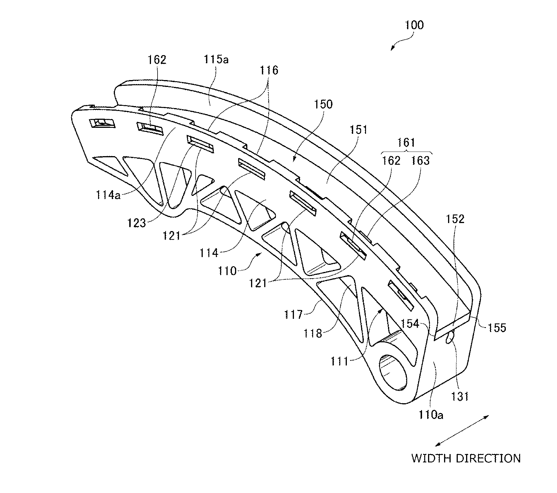
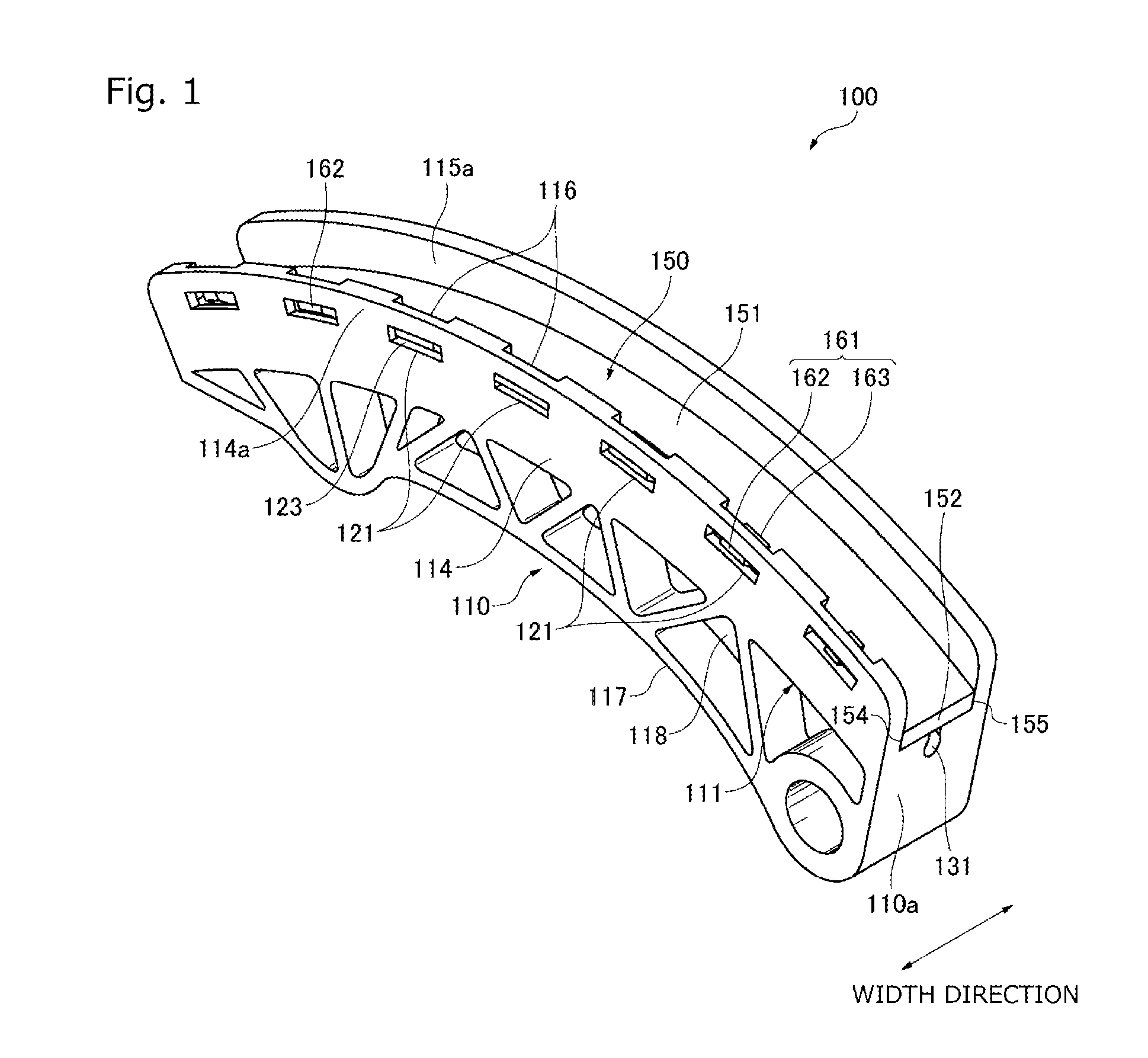
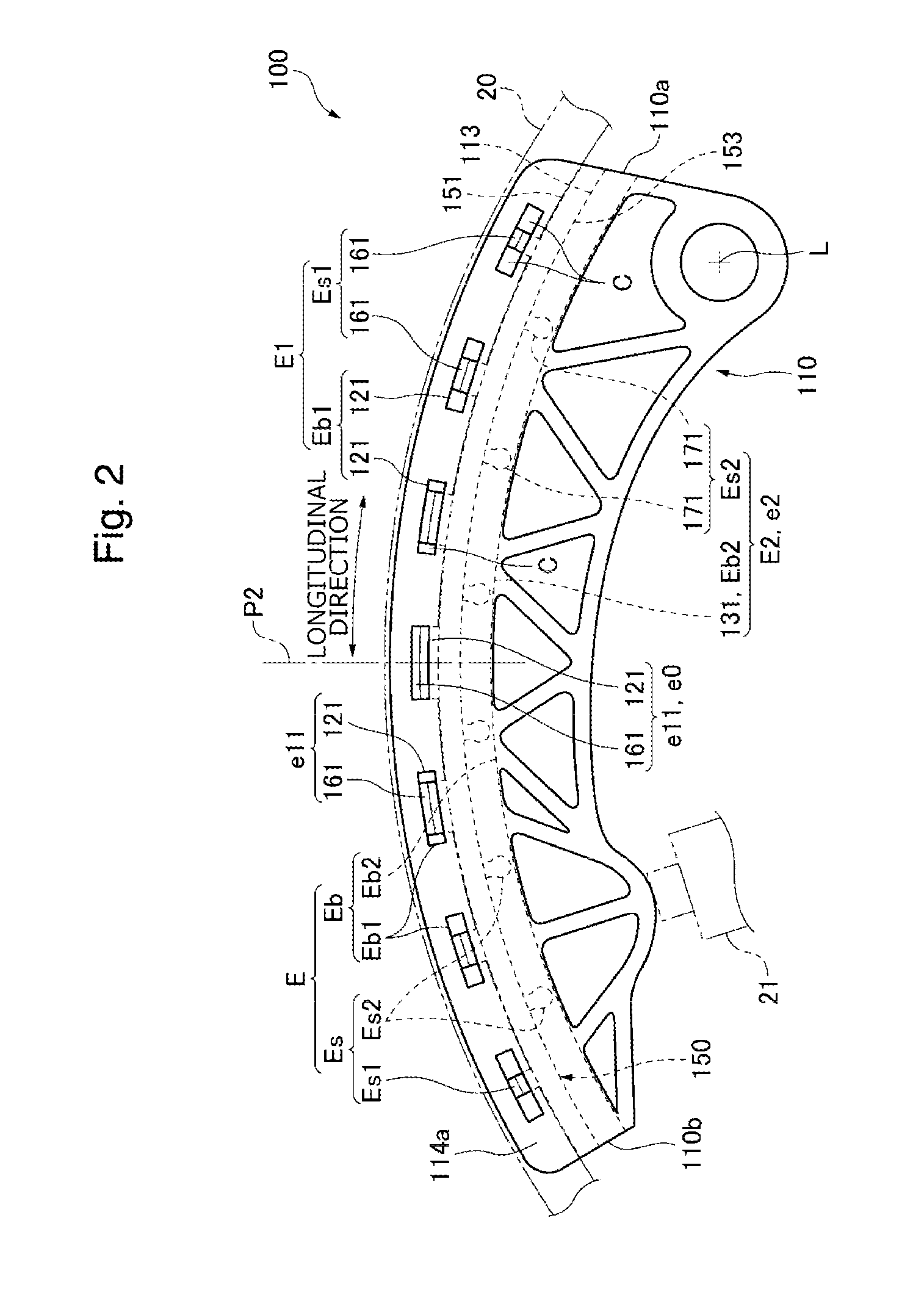
[0053]FIG. 1 to FIG. 7 are diagrams for explaining Embodiment 1 of the present invention.

[0054]Referring to FIG. 1 and FIG. 2, the chain guide 100 (hereinafter, “guide”), or the guide for a flexible transmission member for guiding a chain 20, or the flexible transmission member, along a running direction thereof, is used in a wrapping transmission system, more specifically a timing wrapping transmission system, used in an engine, or a machine, in Embodiment 1 of the present invention.

[0055]This transmission includes an endless chain 20, a sprocket assembly formed by a plurality of sprockets on which the chain 20 is passed over, the guide 100 that forms a guide system brought into sliding contact with the chain 20 as it runs when driven by a drive sprocket included in the sprocket assembly, and a tensioner 21 that applies pressure on the guide 100. The guide 100 is a movable guide pivotally attached to an engine body, or a mounting part of the engine, to be pivotable around a pivot c...

embodiment 2

[0113]Referring to FIG. 10 to FIG. 12, in the chain guide 200 , the base-side lateral mating part Eb1 consists of one, or as in this case, a plurality of, lateral hole parts 221 as first base-side lateral mating elements, and one, or as in this case, a plurality of, lateral fit-in-joints 244 as second base-side lateral mating elements.

[0114]The shoe-side lateral mating part Es1 consists of lateral mating protrusions 261 as first shoe-side lateral mating elements, which are elastic mating elements, and lateral mating protrusions 281 as second shoe-side lateral mating elements, which are elastic mating elements.

[0115]The lateral fit-in-joints 244 are provided to both lips 214a and 215a, which are the protruded portions of the lateral rims 214, 215 of the base, respectively. Each fit-in-joint 244 includes a lateral recess 245 formed on the outer side in the width direction of the lip 214a or 215a as a lateral receiving part that forms a recessed space 247, or a lateral receiving space,...

embodiment 3

[0125]Referring to FIG. 13 to FIG. 15, the guide 300 has one, or as in this case a plurality of, notches 341 recessed downwards in both lips 314a and 315a. Each notch 341 is formed by a pair of stepped portions 342 provided in the height direction and spaced apart from each other in the longitudinal direction, and a bottom part 343 continuous with the stepped portions 342 and extending in the longitudinal direction. The bottom part 343 forms a lateral fit-in-joint 344 as the base-side lateral mating element that forms the base-side lateral mating part Eb1. The bridge 385 is located inside the notch 341.

[0126]The follower surface 382a of the tab 382 abuts on the distal end 348, which is an upper end portion of the bottom part 343, to cause an inward elastic deformation or deflection in the inner support part 384 as the shoe 350 moves downward toward the base 310 to allow the tab 382 to fit in the recess 345.

[0127]The first and second lateral mating elements e11 and e12 are arranged ...


PUM


Abstract

Provided is a chain guide that offers improved assembly efficiency by a more easily engageable interlock structure, operates more quietly by reducing noise caused by collision between mating parts and looseness of the shoe, and improves durability by reducing wear and fatigue of the mating parts. A lateral interlock structure formed by hole parts 121 and mating protrusions 161 restricts relative displacement of the base 110 and the shoe 150. An opposite interlock structure formed by a groove part 131 and mating protrusions 171 restricts relative displacement of the base 110 and the shoe 150 in the height direction. The mating protrusions 161 and 171 are elastic mating elements. The lateral interlock structure and the opposite interlock structure are a snap-fit joint in which a meshed state is achieved through elastic deformation of the mating protrusions 161 and 171 that occurs in a moving process during assembly.

Description

BACKGROUND OF THE INVENTION[0001]1. Field of the Invention[0002]The present invention relates to a guide for a flexible transmission member, in which a shoe in sliding contact with a running flexible transmission member and a base that supports the shoe are joined together by an interlock structure.[0003]The guide is, for example, a chain guide in sliding contact with a chain which is a flexible transmission member and used, for example, for a timing wrapping transmission system used in a car engine.[0004]2. Description of the Related Art[0005]In some conventional guides for a flexible transmission member having a shoe with a running surface in sliding contact with a running flexible transmission member and a base with a support surface for supporting the shoe, it is known that the base and shoe are joined together with an interlock structure formed by a base-side mating part of the base and a shoe-side mating part of the shoe (see, for example, Column 6, Line 17 to Column 7, Line 1...

Claims


Application Information

Patent Timeline
Patent Type & Authority Applications(United States)
IPC IPC(8): F16H7/18
CPCF16H2007/185F16H7/18
Inventor TAKAGI, YUDAIKONNO, MASAHIKO
Owner TSUBAKIMOTO CHAIN CO
Why Eureka
Try Eureka