Refrigerant supply device, cooling device, and cooling system
a cooling device and refrigerant supply technology, applied in indirect heat exchangers, lighting and heating devices, instruments, etc., can solve the problems of ambient temperature rising, high-performance electronic devices consuming a large amount of electric power, and most of the electric power consumption of electronic devices is converted into heat, and achieves a small lateral width
- Summary
- Abstract
- Description
- Claims
- Application Information
AI Technical Summary
Benefits of technology
Problems solved by technology
Method used
Image
Examples
first example embodiment
(First Example Embodiment)
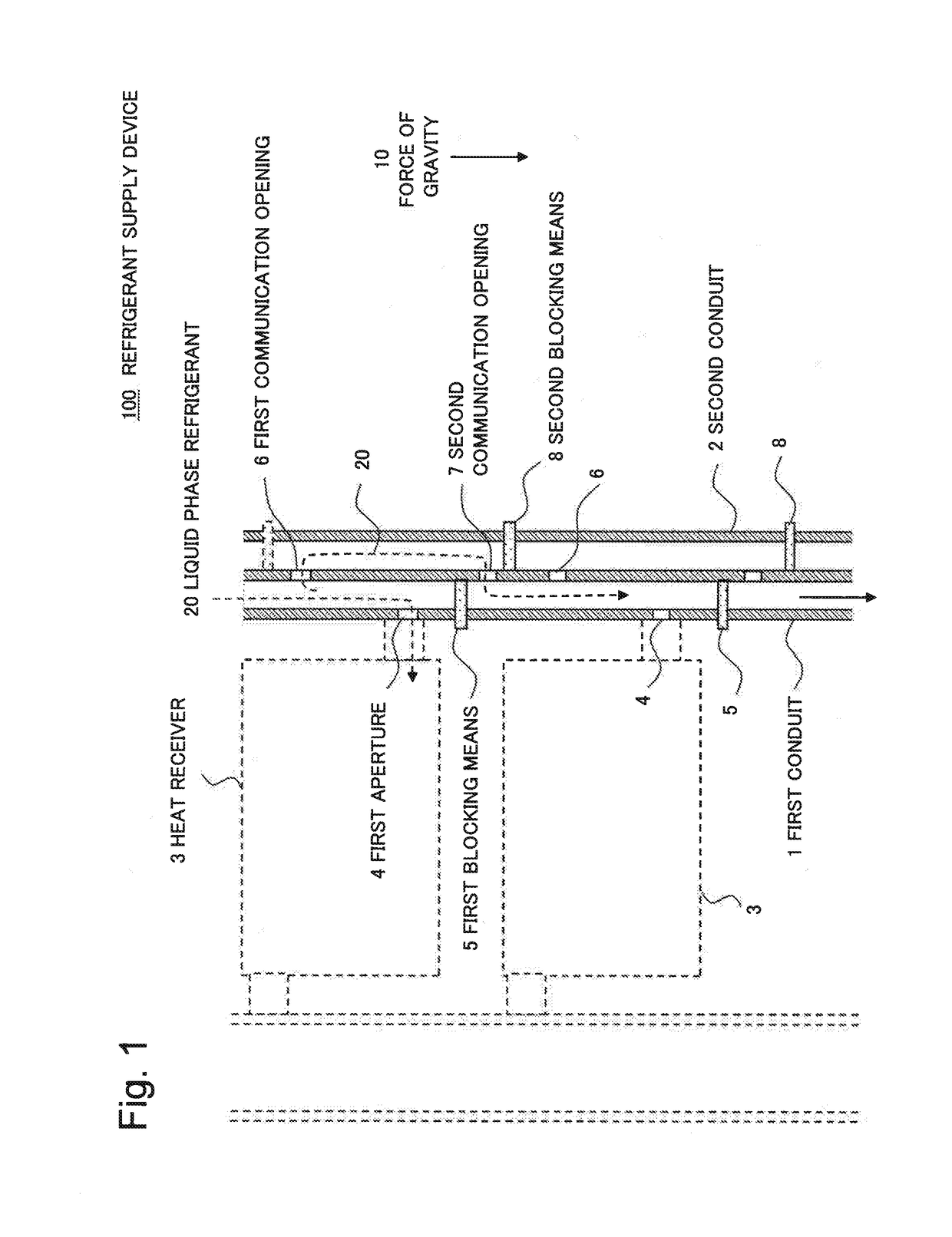
[0027]FIG. 1 is a cross-sectional view illustrating a first example embodiment. The present example embodiment is a refrigerant supply device for distributing, by force of gravity 10, liquid phase refrigerant to heat receivers disposed in a plurality of tiers. A refrigerant supply device according to the present example embodiment 100 includes a first conduit 1 for supplying refrigerant to heat receivers, and a second conduit 2 provided in parallel with the first conduit 1 and sharing part of its conduit wall with the first conduit 1. The first conduit 1 includes a first aperture 4 through which the refrigerant flows to a heat receiver 3 and a first blocking means 5 provided below the first aperture 4 for blocking the first conduit 1. The refrigerant supply device 100 also includes a first communication opening 6 provided above the first aperture 4 and communicating the first conduit 1 and the second conduit 2. The refrigerant supply device 100 also include...
second example embodiment
(Second Example Embodiment)
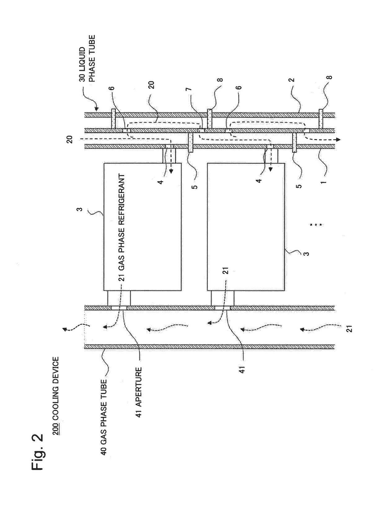
[0030]FIG. 2 is a cross-sectional view illustrating a present example embodiment. The present example embodiment is a cooling device equipped with the refrigerant supply device 100 of the first example embodiment. Herein, the refrigerant supply device 100 is also referred to as liquid phase tube 30 for the sake of simplicity and in light of its function in the cooling device 200.
[0031]The cooling device200 includes a liquid phase tube 30, heat receivers 3 disposed in a plurality of tiers, and a gas phase tube 40. The gas phase tube 40 is provided with apertures 41 at positions corresponding to respective heat exhaust ports of the heat receivers 3, and connected with the heat receivers 3. Note that the heat receivers 3 used in the present example embodiment is an application of so-called ebullient cooling system, that is, heat is absorbed when the liquid phase refrigerant 20 boils in the heat receivers 3. The heat receivers 3 need only to be suitable to the...
third example embodiment
(Third Example Embodiment)
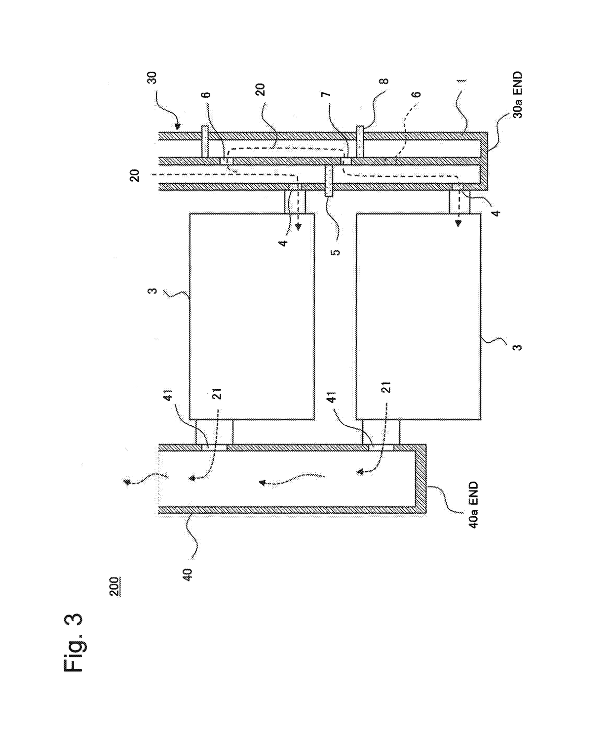
[0035]FIG. 3 is a cross-sectional view illustrating a third example embodiment. The present example embodiment provides a configuration example of the cooling device 200 applied to a heat receiver 3 on the lowest tier. At the end 30a of the liquid phase tube 30 on the lowest tier, the first conduit 1 and the second conduit 2 are both blocked. The end 40a of the gas phase tube 40 is also blocked. It is not necessary to provide a first communication opening 6 at the lowest tier of the liquid phase tube 30 because the liquid phase refrigerant 20 need not be supplied further downward.
[0036]The lowest tier of the liquid phase tube 30 supplies the liquid phase refrigerant 20 to the heat receiver 3 of the lowest tier, and the lowest tier of the gas phase tube 40 receives the gas phase refrigerant from the heat receiver 3 of the lowest tier. Together with the radiator not shown, a closed circuit cooling system is thus formed.
[0037]As described above, the present ex...
PUM
 Abstract
Description
Claims
Application Information
 - R&D
- Intellectual Property
- Life Sciences
- Materials
- Tech Scout
- Unparalleled Data Quality
- Higher Quality Content
- 60% Fewer Hallucinations
Browse by: Latest US Patents, China's latest patents, Technical Efficacy Thesaurus, Application Domain, Technology Topic, Popular Technical Reports.
© 2025 PatSnap. All rights reserved.Legal|Privacy policy|Modern Slavery Act Transparency Statement|Sitemap|About US| Contact US: help@patsnap.com


