

Grating device for radiotherapy equipment, control method thereof and radiotherapy equipment
- Summary
- Abstract
- Description
- Claims
- Application Information
AI Technical Summary
Benefits of technology
Problems solved by technology
Method used
Image

Examples
Embodiment Construction
[0030]The present invention will be further described in detail below in combination with the accompanying drawings and specific embodiments.
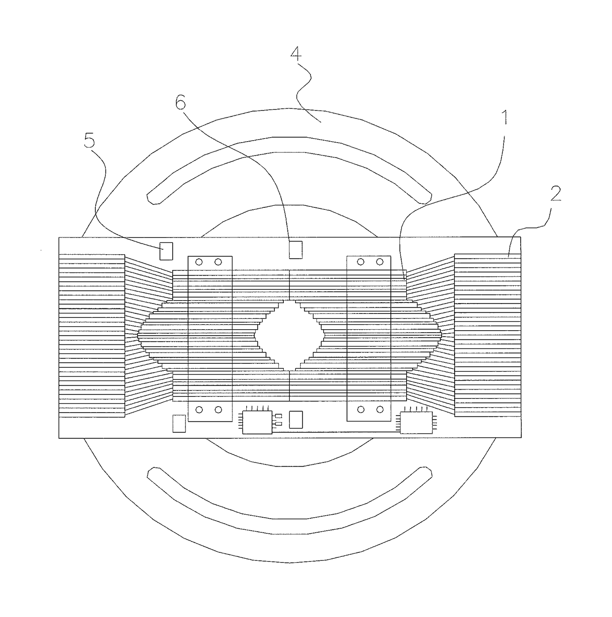
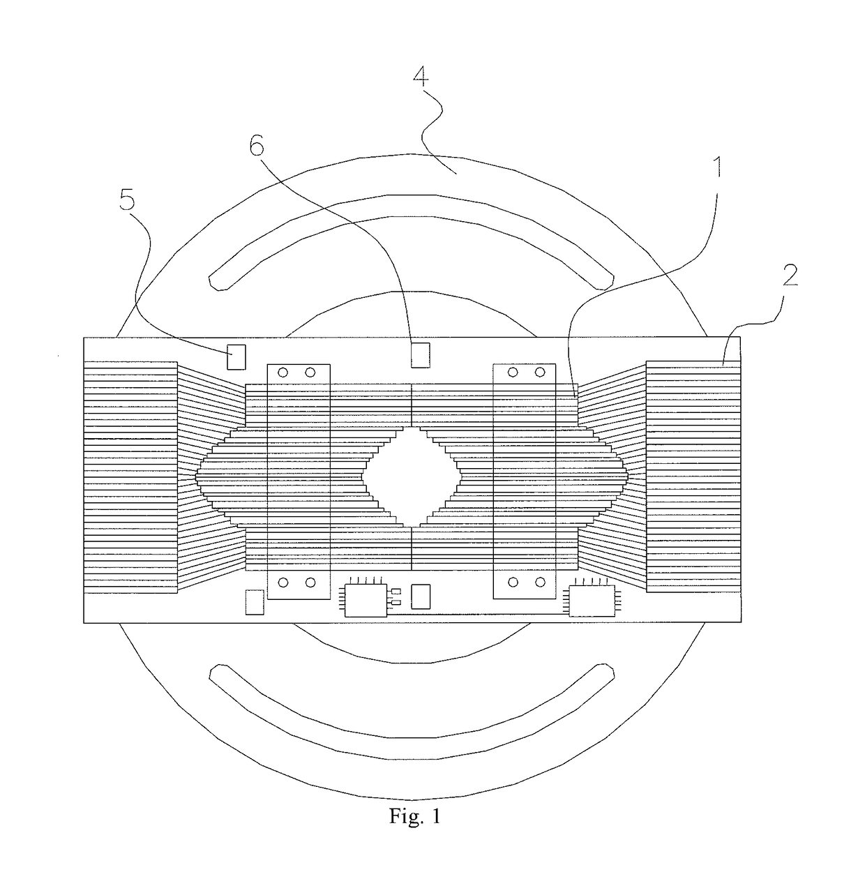
[0031]One embodiment shown in FIGS. 1 and 2 shows a grating device 10 for radiotherapy equipment. The grating device 10 comprises grating blades 1 and a driving device 2 thereof, and further comprises:
[0032]a tail-end position controller 5, used for monitoring whether the tail ends of the grating blades 1 arrive at a preset zero position, i.e., an initial position; and
[0033]a front-end position controller 6, used for monitoring whether the front ends of the grating blades 1 arrive at the middle position, wherein when the two groups of grating blades 1 are at the initial position, front-end projections of the two groups of grating blades 1 are two parallel straight lines, and the middle position is a straight line equidistant from the front ends of the two groups of grating blades.
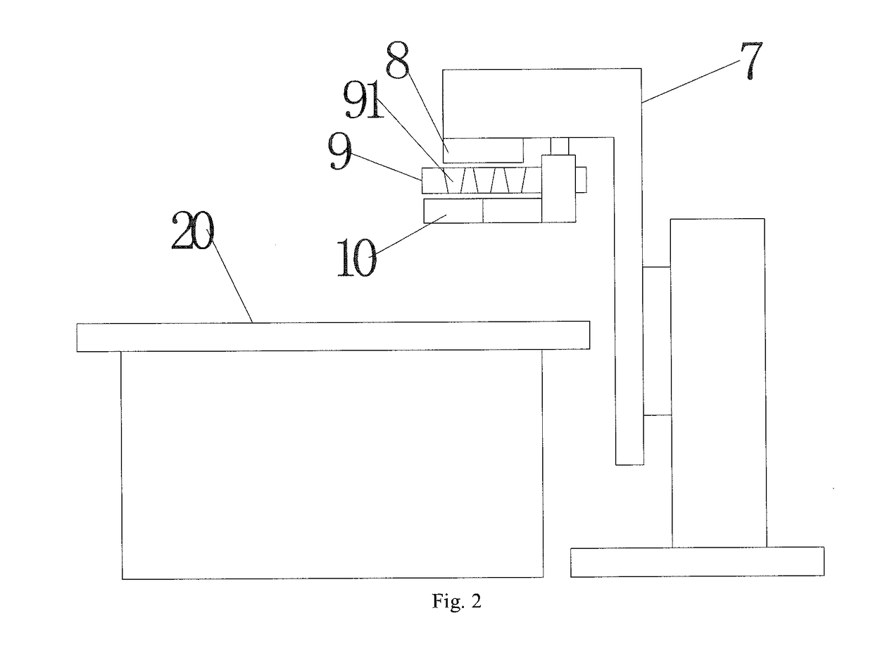
[0034]In FIG. 2, the radiotherapy equipment generally comprises a...
PUM
 Abstract
Description
Claims
Application Information