Developing device and image forming apparatus

a technology of developing device and image forming apparatus, which is applied in the direction of electrographic process apparatus, instruments, optics, etc., can solve the problems of reducing the toner density of the entire developing device, and affecting the development efficiency of the development device. , to achieve the effect of efficient equalization of the developer

Active Publication Date: 2018-04-19
KONICA MINOLTA INC
View PDF3 Cites 4 Cited by
  • Summary
  • Abstract
  • Description
  • Claims
  • Application Information

AI Technical Summary

Benefits of technology

[0012]An object of the present invention is to provide a developing device and an image forming apparatus which enable efficient equalization of a developer entirely along the axial direction of the developing device.

Problems solved by technology

In such a configuration, in the case where the size of the developing device is increased to process sheets which are long in the axial direction such as a B1 sheet, a problem arises in that deviations in toner density are liable to be large along the axial direction since the toner is mixed from the upstream side in the moving direction of the developer.
In the configuration disclosed in Japanese Examined Utility Model (Registration) Application Publication No. 50-27333, however, when images in which one part of the image corresponding to one of first and second regions B1 and B2 has an extremely greater amount of toner than the other part corresponding to the other region are consecutively formed, for example, a problem may arise in that the states of the developer in first and second regions B1 and B2 cannot be equalized due to an extreme decrease in toner density only in the one part corresponding to one of the regions.
This causes a decrease in toner density in the entire developing device at an early stage of the image formation process of the above-mentioned images, so that the recovery of toner density in the entire developing device takes time.

Method used


Image

  • Developing device and image forming apparatus
  • Developing device and image forming apparatus
  • Developing device and image forming apparatus

Examples


Embodiment Construction

[0060]Hereinafter, one or more embodiments of the present invention will be described with reference to the drawings. However, the scope of the invention is not limited to the disclosed embodiments.

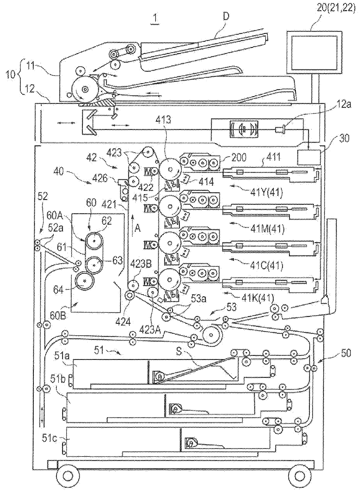
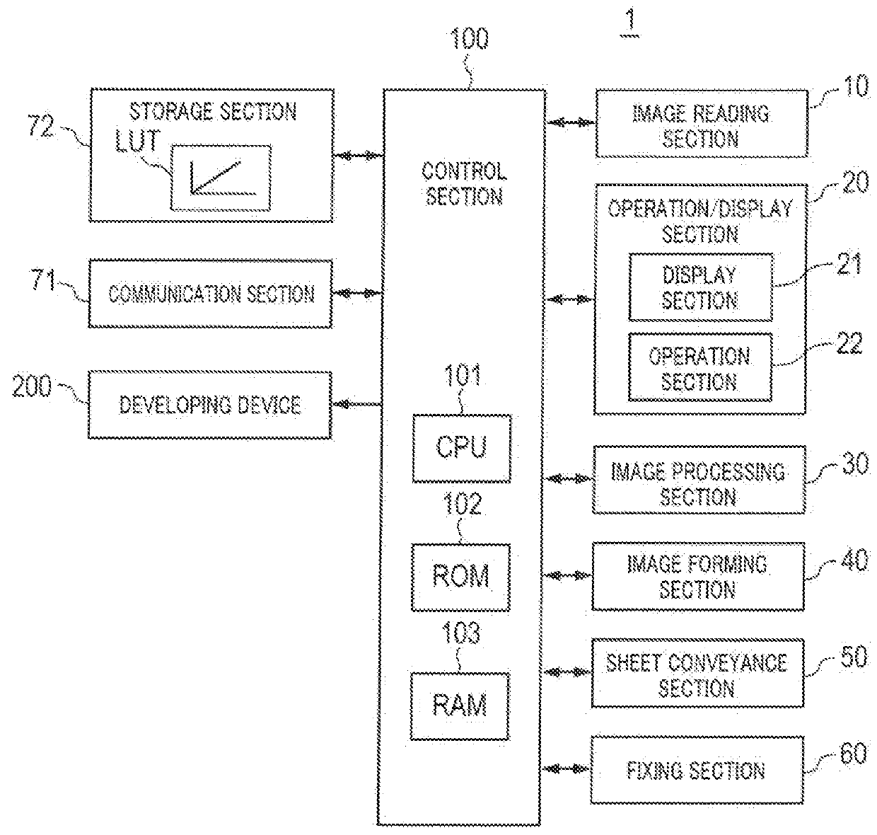
[0061]Hereinafter, an embodiment of the invention is described in detail based on the drawings. FIG. 2 schematically illustrates an entire configuration of image forming apparatus 1 according to an embodiment of the present invention. FIG. 3 illustrates a principal part of a control system of image forming apparatus 1 according to the embodiment of the present invention.

[0062]Image forming apparatus 1 illustrated in FIGS. 2 and 3 is a color image forming apparatus of an intermediate transfer system using electrophotographic process technology. That is, image forming apparatus 1 transfers (primary-transfers) toner images of yellow (Y), magenta (M), cyan (C), and black (K) formed on photoconductor drums 413 to intermediate transfer belt 421, and superimposes the toner images of the four col...


PUM


Abstract

A developing device includes a hardware processor that performs control in which a developer circulation state is switched between a first state and a second state depending on states of the developer in the first and the second regions. The first state is a state in which a developer circulation path is formed in each of the first and the second regions, and the second state is a state in which a single developer circulation path is formed all through the first and the second regions.

Description

CROSS REFERENCE TO RELATED APPLICATIONS[0001]Japanese Patent Application No. 2016-201867 filed on Oct. 13, 2016 and No. 2016-209726 filed on Oct. 26, 2016, including description, claims, drawings, and abstract the entire disclosure are incorporated herein by reference in their entireties.BACKGROUNDTechnological Field[0002]The present invention relates to a developing device and an image forming apparatus.Description of Related Art[0003]In general, an electrophotographic image forming apparatus (such as a printer, a copier, or a fax machine) is configured to irradiate (expose) a charged photoconductor drum (image bearing member) with (to) laser light based on image data to form an electrostatic latent image on the surface of the photoconductor. The electrostatic latent image is then visualized by supplying toner from a developing device to the photoconductor drum on which the electrostatic latent image is formed, whereby a toner image is formed. Further, the toner image is directly o...

Claims


Application Information

Patent Timeline
Patent Type & Authority Applications(United States)
IPC IPC(8): G03G15/08
CPCG03G15/105G03G15/08G03G15/0894G03G15/50G03G15/0893
Inventor OKAMURA, KEITAKAYA, SHUNICHITANAKA, HIDEAKIISHIZUKA, KAZUTERUSAKURAI, SHOTAYUASA, KEI
Owner KONICA MINOLTA INC
Why Eureka
Try Eureka