
Apparatus for making spunbonded nonwoven from continuous filaments

a technology of continuous filaments and filaments, which is applied in the field of apparatus for making spunbonded nonwovens from continuous filaments, can solve the problems of inhomogeneity of spunbonded nonwovens, defect of spunbonded nonwovens, and inability to meet the requirements of continuous filaments, so as to achieve simple and inexpensive measures, prevent unwanted imperfections in the nonwoven web, and influence the effect of filaments

Active Publication Date: 2021-05-11
REIFENHAUSER GMBH & CO MASCHFAB
View PDF5 Cites 0 Cited by
  • Summary
  • Abstract
  • Description
  • Claims
  • Application Information

AI Technical Summary

Benefits of technology

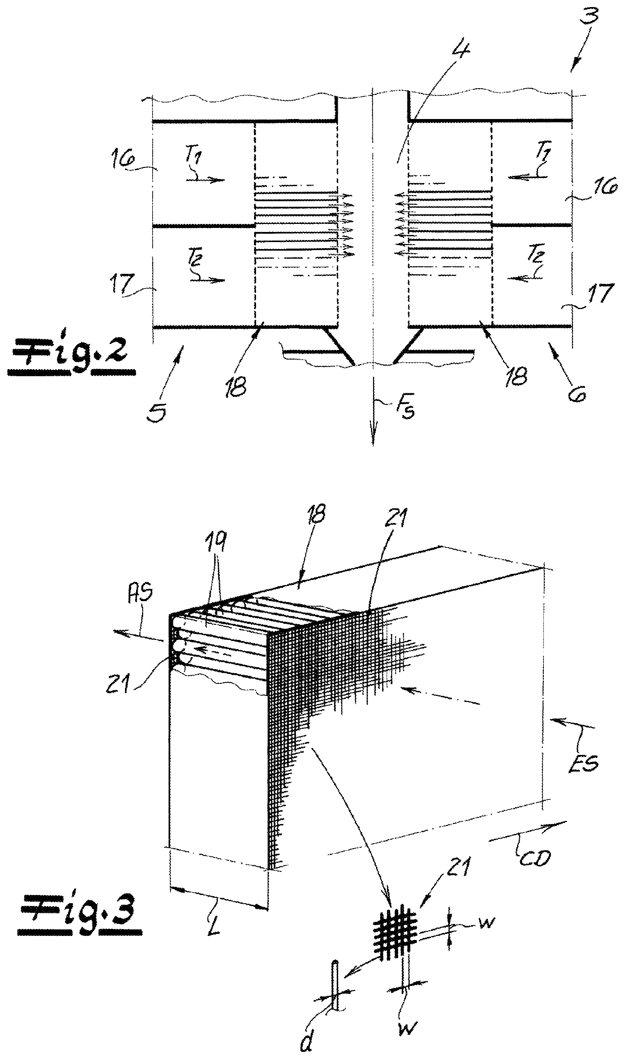
[0011]The flow straighteners according to the invention make it possible, in particular, to achieve a uniform, homogeneous incidence of cooling air over the width of the system and / or in the CD direction. The invention is based on the discovery that, by influencing the cooling, more particularly the cooling air flow in the cooling chamber, and particularly through the special configuration of the flow straightener, a very effective equalization of the filament deposit or fleece deposit is achieved. Due to the cooling according to the invention, and particularly by virtue of the design of the flow straightener, it is possible to produce surprisingly homogeneous spunbonded nonwovens that are largely free of imperfections or defects. Above all, this also applies to higher throughputs and higher yarn speeds as specified in greater detail below.
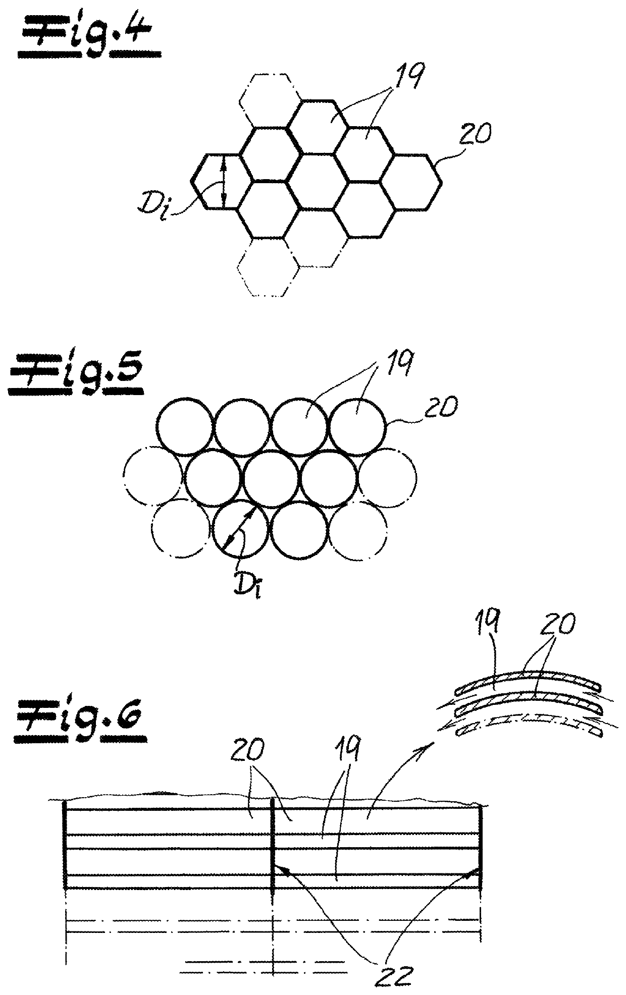
[0023]According to a very preferred embodiment of the invention, the length L of the flow passages of a flow straightener is 15 to 65 mm, preferably 20 to 60 mm, more preferably 20 to 55 mm, and very preferably 25 to 50 mm. Recommendably, the inner diameter or the smallest inner diameter Di of the flow passages is 2 to 15 mm, preferably 3 to 12 mm, more preferably 4 to 11 mm, and very preferably 5 to 10 mm. It lies within the scope of the invention for the flow passages to be compact and closely juxtaposed next to one another in a flow straightener. Preferably, flow passage adjoins the flow passage in a flow straightener, and, according to one embodiment, it is possible for only spacers to be present between the flow passages. It is recommended that the mutual spacing between the flow passages or at least the majority of the flow passages be less than or substantially less than the smallest inner diameter Di of a flow passage. Advantageously, the flow passages are grouped in a flow straightener according to the principle of closest packing.
[0028]According to an especially preferred embodiment of the invention, the subassembly of the cooling chamber and the stretcher or the subassembly of the cooling chamber, the intermediate passage, and the tunnel is embodied as a closed system. “Closed system” means particularly that, apart from the supply of cooling air into the cooling chamber, no further air supply takes place in this unit. The flow straighteners that are used according to the invention are distinguished, above all, by special advantages in such a closed system. An especially simple and effective equalization of the air flow, more particularly of the cooling air flow, is possible here.
[0032]The invention is based on the discovery that, with the apparatus according to the invention, spunbonded nonwovens of optimal quality and above all with homogeneous properties over their surface extension can be achieved. Imperfections or defects in the nonwovens, more particularly in the nonwoven surfaces, can be completely prevented or at least largely minimized. In particular, these advantages can also be achieved at high throughputs of the apparatus of greater than 150 kg / h / m or greater than 200 kg / h / m. By virtue of the inventive configuration of the air-supply manifolds and the flow straighteners, an optimal cooling air supply into the cooling chamber is ensured, which ultimately leads to the advantageous properties of the spunbonded nonwoven web. A very uniform or homogeneous cooling air supply can be achieved in the context of the invention, and, due to this advantageous supply of cooling air, the filaments are positively influenced in that unwanted imperfections in the nonwoven web can be prevented or largely minimized. Nevertheless, the apparatus according to the invention can be realized with relatively simple and inexpensive measures. It is thus also characterized by its cost-effectiveness.

Problems solved by technology

Many of these known apparatuses have the disadvantage that the spunbonded nonwovens made with them are not always sufficiently homogeneous over their entire surface.
Many spunbonded nonwovens have objectionable inhomogeneities shaped as imperfections or defects.
One typical imperfection in such spunbonded nonwovens is caused by so-called “drops.” These arise as a result of the tearing-off of one or more soft or molten filaments, resulting in a melt accumulation that causes a defect in the spunbonded nonwoven.
Many spunbonded nonwovens or spunbonded fleeces made by known processes exhibit such inhomogeneities, especially if high throughputs are used in their production.

Method used


Image

  • Apparatus for making spunbonded nonwoven from continuous filaments
  • Apparatus for making spunbonded nonwoven from continuous filaments
  • Apparatus for making spunbonded nonwoven from continuous filaments

Examples


Embodiment Construction

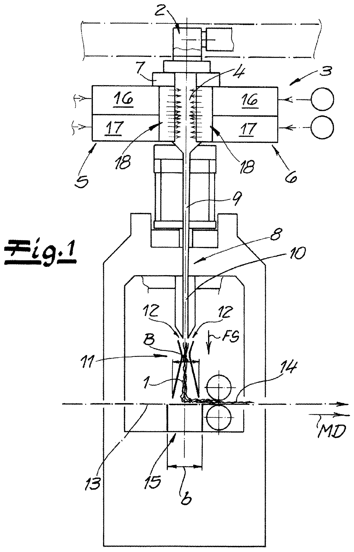
[0040]As seen in FIG. 1 an apparatus according to the invention for manufacturing spunbonded nonwovens from continuous filaments 1, particularly from continuous thermoplastic filaments 1 has a spinneret 2 for spinning the continuous filaments 1. These spun continuous filaments 1 are introduced in a vertical and downward filament-travel direction FS into a cooler 3 with a cooling chamber 4 flanked on opposite sides by air-supply manifolds 5 and 6. The cooling chamber 4 and the air-supply manifolds 5 and 6 are spaced transverse to a machine direction MD perpendicular to the direction FS and thus in the CD direction of the apparatus. Cooling air is introduced from the oppositely situated air-supply manifolds 5 and 6 into the cooling chamber 4. Preferably and here, a monomer extractor 7 is provided between the spinneret 2 and the cooler 3. With this monomer extractor 7, objectionable gases produced by the spinning process can be removed from the apparatus. These gases can be monomers, o...


PUM

PropertyMeasurementUnit
thicknessaaaaaaaaaa
thicknessaaaaaaaaaa
lengthaaaaaaaaaa

Abstract

An apparatus for making spunbonded nonwoven has a spinneret for emitting the continuous filaments in a filament-travel direction, a cooling chamber downstream in the direction from the spinneret and receiving the filaments, and two air-supply manifolds flanking the chamber for feeding cooling air thereinto transverse to the direction. A flow straightener for equalizing flow of the cooling air on the filaments is provided in at least one of the air-supply manifolds and has passage walls forming a plurality of flow passages that extend transversely to a filament-travel direction. A flow cross section of the flow straightener is greater than 85% (preferably more than 90%) of a cross-sectional size of the straightener, a ratio of a length L of the flow passages to an inner diameter Di of the flow passages L / Di is 1 to 15.

Description

FIELD OF THE INVENTION[0001]The present invention relates to the manufacture of spunbonded nonwoven. More particularly this invention concerns an apparatus for making spunbonded nonwoven from continuous filaments.BACKGROUND OF THE INVENTION[0002]A known apparatus for making spunbonded nonwovens from continuous filaments, particularly from continuous thermoplastic filaments, comprises a spinneret for spinning the continuous filaments, a cooling chamber for cooling the spun filaments with cooling air, a respective air-supply manifold is provided on each of the opposing sides of the cooling chamber for feeding cooling air into the cooling chamber from the respective oppositely situated air-supply manifolds, and flow straighteners in the air-supply manifolds for equalizing the cooling air fed from the air-supply manifolds.[0003]In the context of the invention, “spunbonded nonwoven” refers particularly to a spunbond fabric that is made by the spunbond process. Continuous filaments differ...

Claims


Application Information

Patent Timeline
Patent Type & Authority Patents(United States)
IPC IPC(8): D01D5/092D04H3/16
CPCD01D5/092D04H3/16D10B2321/022D10B2331/04D04H3/11D04H3/005D01D5/088D01D5/0985D01D5/098D02J13/00D04H13/00
Inventor FREY, DETLEFTIEDT, TRISTANNITSCHKE, MICHAELNEUENHOFER, MARTINGEUS, HANS-GEORG
Owner REIFENHAUSER GMBH & CO MASCHFAB
Learn More