Flow velocity distribution equalizing apparatus

a technology of flow velocity and equalizing apparatus, which is applied in mechanical equipment, lighting and heating equipment, machines/engines, etc., can solve the problems of reduced life of catalysts, demerits of catalysts, and high cost and short life, and achieve the effect of short li

Inactive Publication Date: 2014-10-16
KAWASAKI HEAVY IND LTD
View PDF0 Cites 0 Cited by
  • Summary
  • Abstract
  • Description
  • Claims
  • Application Information

AI Technical Summary

Benefits of technology

[0003]The catalytic combustor mounted on gas turbine engines has advantage relative to the conventional art, including little emission of NOx when an inflow gas is combusted by catalytic reaction and capability of oxidizing a low concentration methane, which cannot be ordinarily combusted and is therefore emitted to the atmosphere. Therefore, the catalytic combustor referred to above is considered superior in dealing with environment related issues including, for example, low emission and global warming. On the other hand, the catalytic combustor has some demerits such as, for example, expensiveness and short life.

Problems solved by technology

On the other hand, the catalytic combustor has some demerits such as, for example, expensiveness and short life.
Specifically, catalytic combustion under a high pressure condition such as in the gas turbine engine, particularly where the flow velocity distribution of a compressed gas containing a fuel at the inlet to the catalytic combustor varies considerably, is liable to develop uneven temperature distribution within the catalyst, accompanied by reduction in life of the catalyst.
It has, however, been found that the use of the flow passage having a long and straight length requires a large piping space which leads to an increase of the size.
Where the rectifier plate is used, the pressure loss tends to increase and, if the flow velocity distribution on an upstream side of the rectifier plate changes considerably, the rectifier plate, which is a fixed throttling plate, is incapable to accommodate.

Method used


Image

  • Flow velocity distribution equalizing apparatus
  • Flow velocity distribution equalizing apparatus
  • Flow velocity distribution equalizing apparatus

Examples


Embodiment Construction

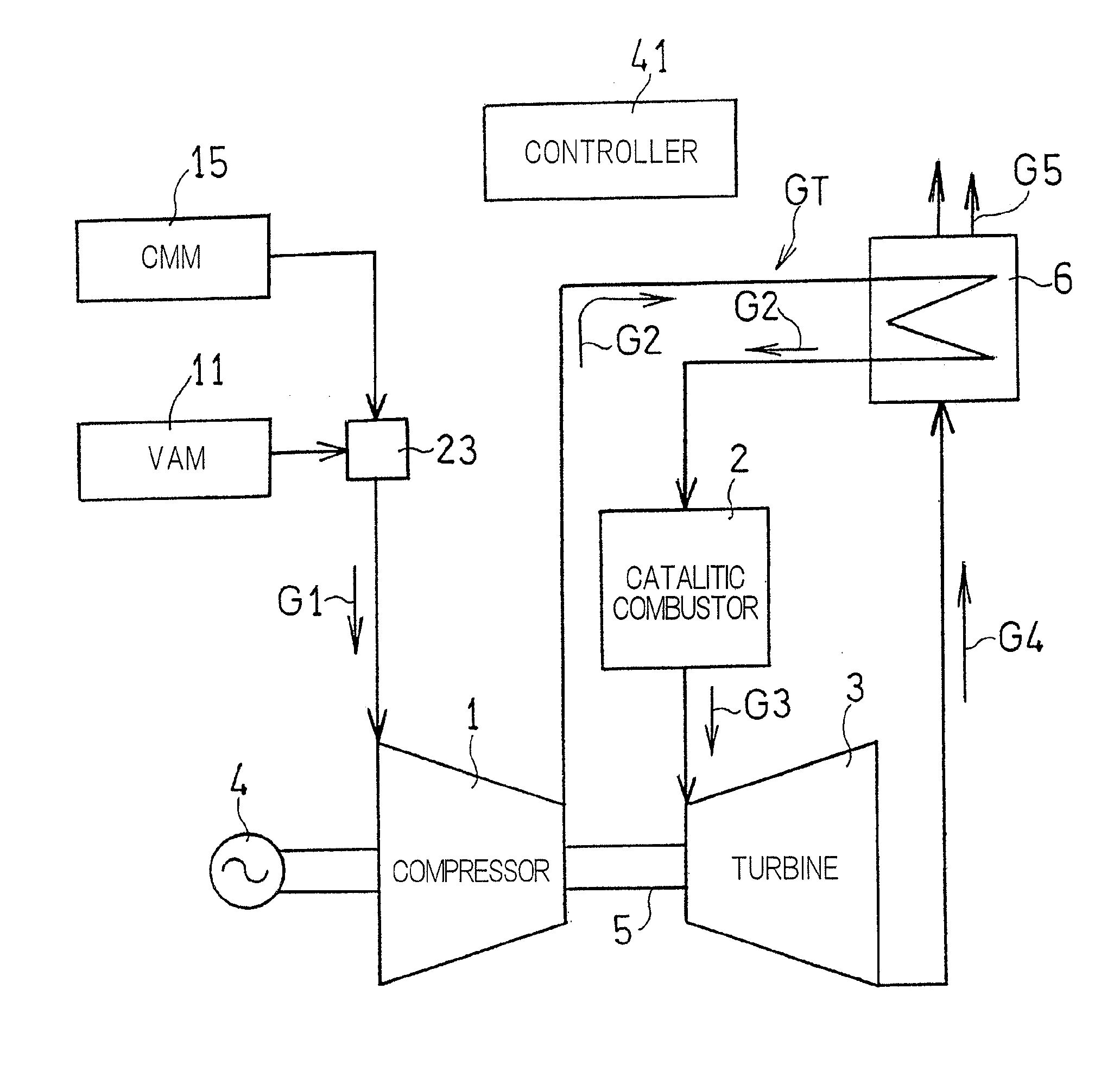
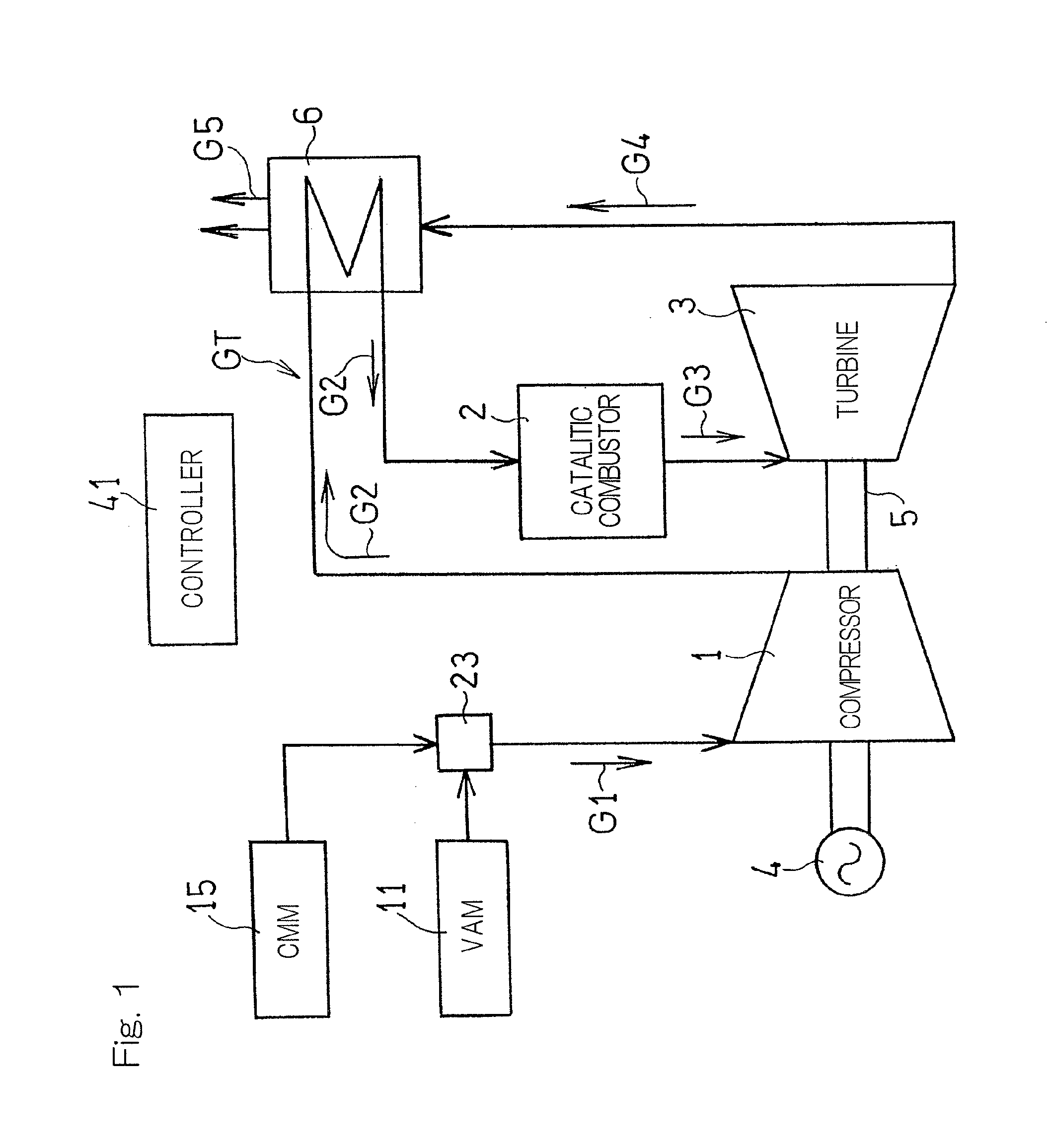
[0023]Reference will now be made to the accompanying drawings for the details of a flow velocity distribution equalizing apparatus designed in accordance with an embodiment of the present invention. In particular, FIG. 1 illustrates a block diagram showing a schematic structure of a gas turbine engine GT employing the flow velocity distribution equalizing apparatus in accordance with an embodiment of the present invention, in which a gas turbine engine GT configured to utilize a lean fuel is illustrated as an example. This gas turbine engine GT includes a compressor 1, a catalytic combustor 2 utilizing a catalyst such as, for example, platinum and / or palladium, and a turbine 3. This gas turbine engine GT provides an output to drive an electric power generator 4.

[0024]As a low calorie fuel gas used in the gas turbine engine GT, the following gases may be employed. Specifically, from a VAM (ventilation air methane) supply source, a VAM produced in coal mines is supplied and a CMM (coa...


PUM


Abstract

An apparatus for equalizing flow velocity distribution of a fuel gas supplied into a catalytic combustor includes a rectification vane and a rectification plate in an inlet chamber of the catalyst combustor. The inlet chamber has a round transverse sectional shape and includes an inflow port that allows the fuel gas to inflow radially, and an outflow port for discarding the fuel gas axially. The rectification vane has a front edge oriented towards the inflow port, and a rectifying surface ramified from the front edge so as to extend towards a cylindrical inner wall surface of the inlet chamber such that swirling flow of the fuel gas flown into the inlet chamber, that flows towards the inflow port along the cylindrical inner wall surface, is generated. The rectification plate is located at the outflow port and has openings for allowing the fuel gas to flow therethrough.

Description

CROSS REFERENCE TO THE RELATED APPLICATION[0001]This application is a continuation application, under 35 U.S.C. §111(a), of international application No. PCT / JP2012 / 083592, filed Dec. 26, 2012, which claims priority to Japanese patent application No. 2011-288019, filed Dec. 28, 2011, the disclosure of which are incorporated by reference in their entirety into this application.DESCRIPTION OF RELATED ART[0002]The present invention relates to an apparatus for equalizing a flow velocity distribution of a gas flowing into a catalytic combustor in a gas turbine engine.SUMMARY OF THE INVENTION[0003]The catalytic combustor mounted on gas turbine engines has advantage relative to the conventional art, including little emission of NOx when an inflow gas is combusted by catalytic reaction and capability of oxidizing a low concentration methane, which cannot be ordinarily combusted and is therefore emitted to the atmosphere. Therefore, the catalytic combustor referred to above is considered sup...

Claims


Application Information

Patent Timeline
Patent Type & Authority Applications(United States)
IPC IPC(8): F02C7/22
CPCF02C7/22F23R3/40F23L15/00F23R3/04Y02E20/34
Inventor DOURA, YASUSHIOGATA, MASAHIROTANAKI, KOUSUKE
Owner KAWASAKI HEAVY IND LTD
Why Eureka
Try Eureka