Multiplexer, transmission apparatus, and reception apparatus

a transmission apparatus and multi-channel technology, applied in the field of multi-channel transmission apparatus and reception apparatus, can solve the problems of difficult to ensure low-loss characteristics in the pass band of the multiplexer, and the difficulty of achieving impedance matching for a plurality of filter elements using only the above-mentioned impedance matching circuit, so as to achieve the effect of significantly reducing or preventing the loss of insertion in the pass band of each filter elemen

Active Publication Date: 2018-05-31
MURATA MFG CO LTD
View PDF34 Cites 4 Cited by
  • Summary
  • Abstract
  • Description
  • Claims
  • Application Information

AI Technical Summary

Benefits of technology

[0008]Preferred embodiments of the present invention provide a multiplexer, a transmission apparatus, and a reception apparatus with insertion losses that are significantly reduced or prevented in a pass band of each filter element.

Problems solved by technology

However, as the number of bands to be used increases, it becomes more difficult to achieve impedance matching for a plurality of filter elements using only the above-mentioned impedance matching circuit.
In this case, however, a notch waveform formed by the LC resonant circuit described in Japanese Unexamined Patent Application Publication No. 2004-104799 may be unexpectedly generated within a pass band of the multiplexer.
As a result, it becomes difficult to ensure low-loss characteristics in the pass band of the multiplexer.

Method used


Image

  • Multiplexer, transmission apparatus, and reception apparatus
  • Multiplexer, transmission apparatus, and reception apparatus
  • Multiplexer, transmission apparatus, and reception apparatus

Examples


first preferred embodiment

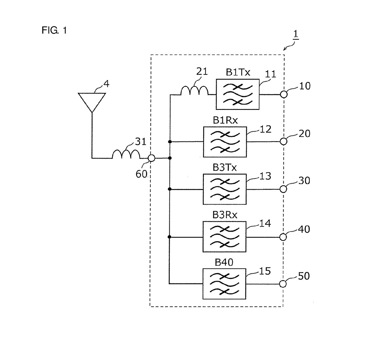
[0066]FIG. 1 is a circuit diagram of the multiplexer 1 according to a first preferred embodiment of the present invention. As shown in FIG. 1, the multiplexer 1 includes transmission filters and 13, reception filters 12 and 14, a transmission and reception filter 15, an inductance element 21, a common terminal 60, transmission input terminals 10 and 30, reception output terminals 20 and 40, and an input and output terminal 50. The multiplexer 1 is connected to an antenna element 4 with an inductance element 31 therebetween, the inductance element 31 being connected in series to the common terminal 60 and the antenna element 4. The inductance element 31 defines and functions as an impedance matching element.

[0067]The transmission filter 11 is a band pass filter which inputs a transmission signal generated at a transmission circuit (for example, an RFIC or the like) via the transmission input terminal 10, performs filtering with the transmission pass band (for example, from about 1920...

second preferred embodiment

[0135]As illustrated in FIG. 12, a multiplexer 1A according to a second preferred embodiment of the present invention includes the same configuration as that of the first preferred embodiment, but a capacitance element 22 is preferably connected in parallel between a reference terminal (for example, ground) and a connection point of the inductance element 21 and the transmission filter 11. The second preferred embodiment provides advantages similar to those of the first preferred embodiment.

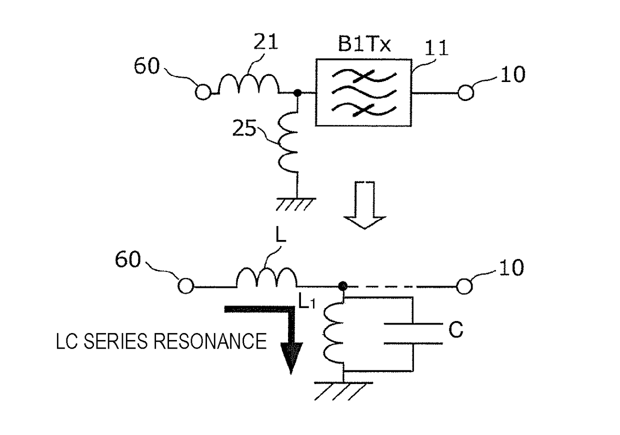
[0136]FIG. 13 is a diagram showing an LC series resonant circuit including an inductor element, a capacitor element, and a filter element according to the second preferred embodiment of the present invention. As shown in FIG. 13, for example, in the case where the inductance element 21 is connected in series between the transmission filter 11 and the common terminal 60 and the capacitance element 22 is connected in parallel between a reference terminal and the connection point of the first induct...

third preferred embodiment

[0137]As illustrated in FIG. 14, a multiplexer 1B according to a third preferred embodiment of the present invention includes the same configuration as that of the first preferred embodiment, but a second inductance element 23 is preferably connected in series between the inductance element 21 and the transmission filter 11. The third preferred embodiment provides advantages similar to those of the first preferred embodiment.

[0138]FIG. 15 is a diagram showing an LC series resonant circuit including a first inductor element, a second inductor element, and a filter element according to the third preferred embodiment of the present invention. As shown in FIG. 15, for example, in the case where the first inductance element 21 and the second inductance element 23 are connected in series between the transmission filter 11 and the common terminal 60, LC series resonance is generated at a path from the common terminal 60 to a reference terminal (for example, ground) by an inductive componen...


PUM


Abstract

A multiplexer includes a common terminal connected to an inductance element at a connection path with an antenna element, filter elements including different pass bands and connected to the antenna element with the common terminal therebetween, and an inductance element arranged in series between a transmission filter with a largest capacitance when viewed from the antenna side among the filter elements and the common terminal. An inductive component of the inductance element and a capacitive component of the transmission filter element define an LC series resonant circuit, and a resonant frequency of the LC series resonant circuit is lower than any of pass bands of the filter elements.

Description

CROSS REFERENCE TO RELATED APPLICATIONS[0001]This application claims the benefit of priority to Japanese Patent Application No. 2016-032662 filed on Feb. 24, 2016. The entire contents of this application are hereby incorporated herein by reference.BACKGROUND OF THE INVENTION1. Field of the Invention[0002]The present invention relates to a multiplexer, a transmission apparatus, and a reception apparatus.2. Description of the Related Art[0003]In recent years, cellular phones have required that a single terminal support multiple frequency bands and multiple wireless systems, that is, multiband and multimode terminals have been required. To this end, a multiplexer for separating high-frequency signals according to a radio carrier frequency (band) is arranged immediately below an antenna. As a plurality of band pass filters of a multiplexer, elastic wave filters exhibiting low-loss characteristics in a pass band and steepness near the pass band are used.[0004]Japanese Unexamined Patent A...

Claims


Application Information

Patent Timeline
Patent Type & Authority Applications(United States)
IPC IPC(8): H04B1/00H04B1/40H04J1/04
CPCH04B1/0057H04B1/40H04J1/045
Inventor ARAKI, MASATO
Owner MURATA MFG CO LTD
Why Eureka
Try Eureka