Dynamically tunable radio frequency filter and applications

a radio frequency filter and dynamic technology, applied in the field of dynamic tunable radio frequency filters, can solve the problems of introducing a high level of spurious noise, adding spurious noise to the process, and no online devices, and achieve the effect of precise notch and bandpass filters

Pending Publication Date: 2021-08-19
BELKIN SAM
View PDF33 Cites 0 Cited by
  • Summary
  • Abstract
  • Description
  • Claims
  • Application Information

AI Technical Summary

Benefits of technology

[0049]FIG. 11 shows the effect of variable LOs in a two 2-mixer embodiment.
[0050]FIG. 12 shows the effect of managing the cutoff frequencies of two filters (LPF and HPF or HPF and LPF) to create precise notch and bandpass filters.

Problems solved by technology

However, such filter designs generally include inherent L, C, and R parasitic values, which may cause latency.
Further, such integrated filters include nonlinear devices that generally tend to add spurious noise to the process.
Use of conventional mixers generally tends to introduce a high level of spurious noise.
Prior art filters that use various well-known passive and active circuits, and all those that use prior art mixers, typically add noise signal due to nonlinearity of the mixing circuit, because nonlinearity has been understood to be an inherent and fundamental characteristic of all mixers.
. . ” In nonlinear devices, unavoidable spurious signal products limit the performance of the design, and therefore of all filter designs that use conventional nonlinear mixers.
Problems of prior art filters in general include complexity / cost required to achieve high Q with low noise, a lack of tuning agility (center frequency and bandwidth), high insertion loss, the inability to mitigate group delay, and the inability to address interferers in adjacent channels.
However, nothing was found in the prior art in which the frequency spectrum conversion process was accompanied by filtering to optimize signal quality.

Method used

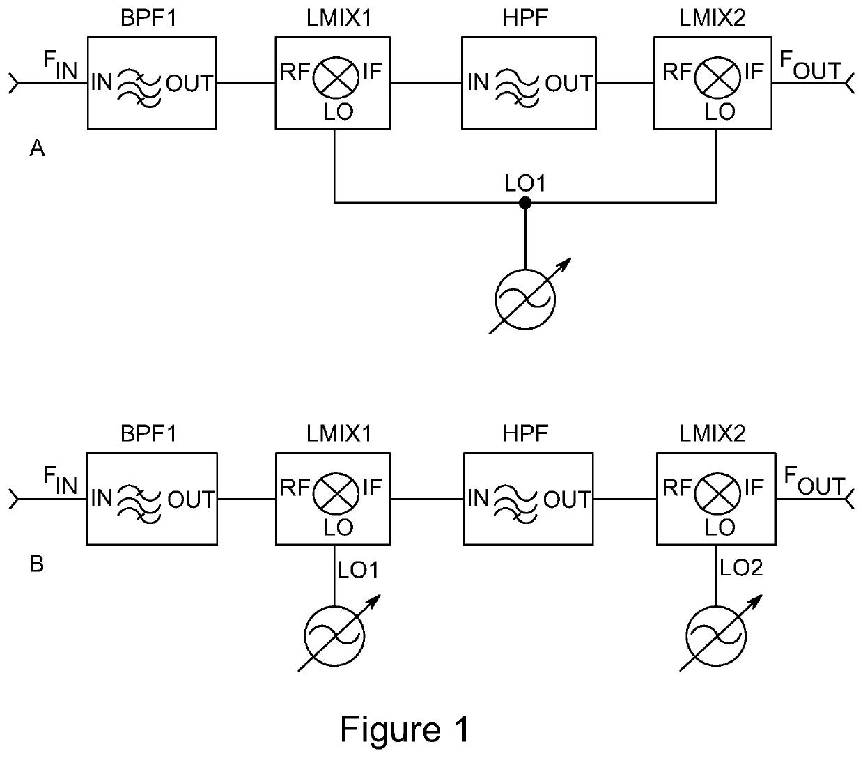
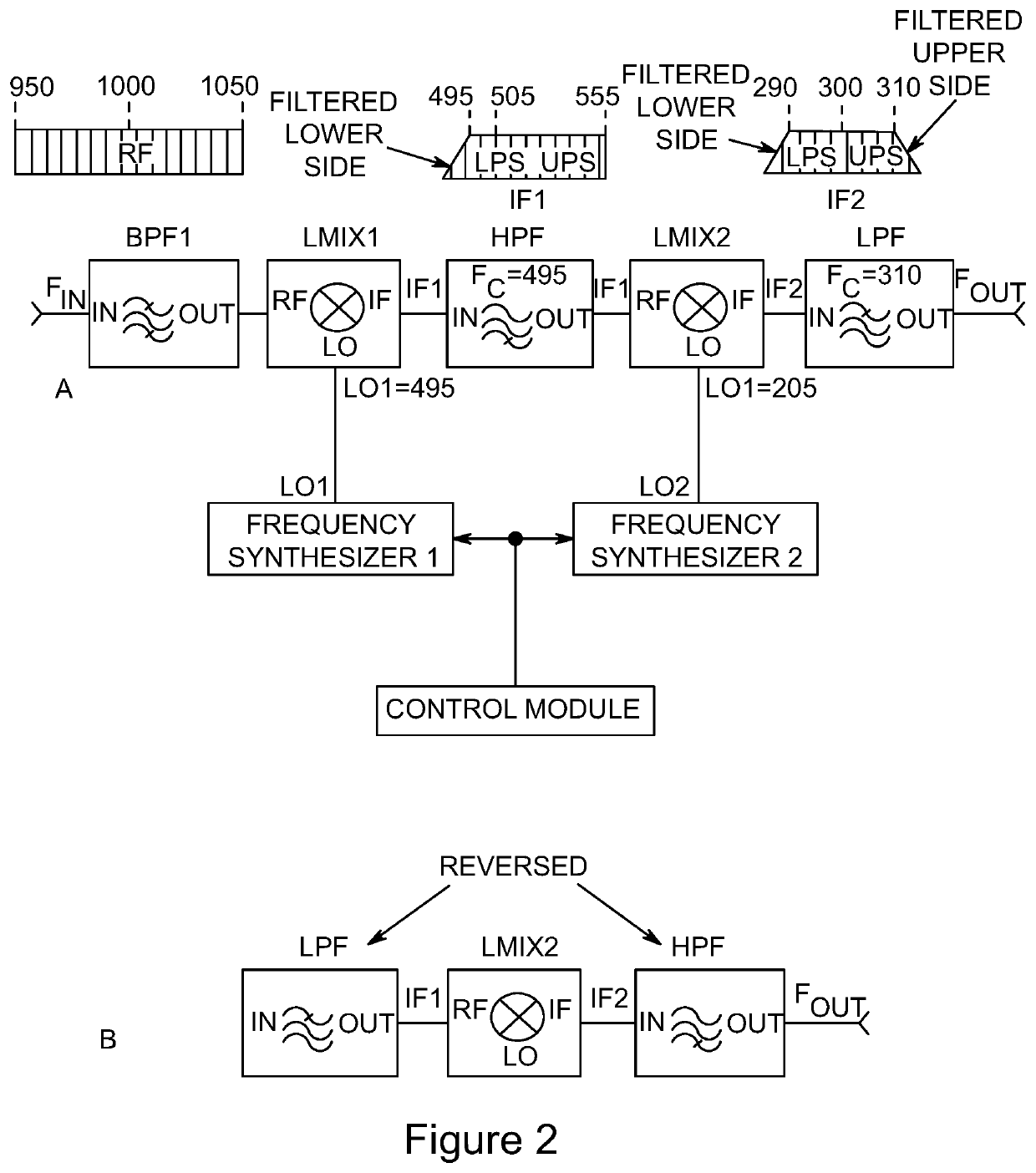
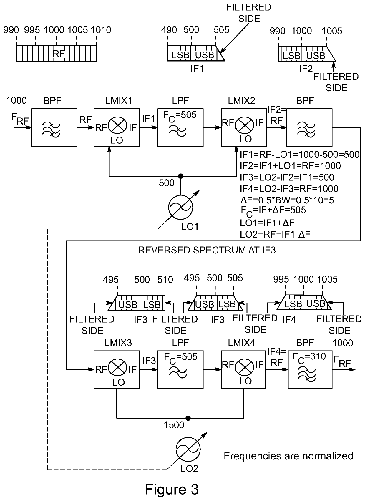

Image

  • Dynamically tunable radio frequency filter and applications
  • Dynamically tunable radio frequency filter and applications
  • Dynamically tunable radio frequency filter and applications

Examples


Embodiment Construction

[0052]In the following description, numerous specific details are set forth in order to provide an enabling understanding of radio frequency filter designs that embody principles of the present invention. To one skilled in the art, most of the figures provide sufficient description as to enable practice of the invention. Also, one skilled in the art may practice the invention without some specific details and with minor variations of the circuitry, while remaining within the bounds of the invention. Throughout this description, the embodiments and examples shown should be considered as exemplars, rather than as limitations on the invention. That is, the following description and attached figures show various examples for the purposes of illustration. However, these examples should not be construed in a limiting sense as they are merely intended to provide examples of the invention and its applications rather than to disclose all possible implementations of the present invention.

[005...


PUM


Abstract

A family of radio frequency (RF) filter circuits that use radio frequency linear mixers to controllably separate desired frequency spectrum from undesired frequency spectrum, and convert signals from one frequency to another, permitting inclusion in a closed- or open-loop control circuit that supports rapid dynamic manipulation of the filter circuit's center frequency and bandwidth.

Description

CROSS-REFERENCE TO RELATED APPLICATIONS[0001]This application claims the benefit of priority of U.S. Provisional Application No. 62 / 977,654, filed 17 Feb. 2020 for Sam Belkin, which is incorporated herein by reference in its entirety.BACKGROUND OF THE INVENTION1. Field[0002]The present invention relates generally to radio frequency (RF) circuits and to the use of filters to separate or convert the spectrum of a complex RF signal.2. Background[0003]In the world of RF and microwave circuits, which includes broadcast television and radio, radar, cellular telephony, electronic warfare, and all other radios, as well as radio frequency signals transmitted via cable or optical means, a complex band of signals is captured by a source such as an antenna, making it necessary to select or reject (pass or suppress) portions of the applied spectra using filtering circuits, thus enabling focus upon those frequencies and signals from which meaningful information will be extracted or, in the case o...

Claims


Application Information

Patent Timeline
Patent Type & Authority Applications(United States)
IPC IPC(8): H04B1/00H04B1/30
CPCH04B1/0057H04B2001/307H04B1/0096H04B1/30
Inventor BELKIN, SAM
Owner BELKIN SAM
Why Eureka
Try Eureka