Camera Mount

a technology for cameras and mounts, applied in the field of cameras, can solve the problems of not being able to achieve the desired camera position or camera angle on the plane of attachmen

Inactive Publication Date: 2005-12-01
HEIBEL THOMAS S
View PDF5 Cites 78 Cited by
  • Summary
  • Abstract
  • Description
  • Claims
  • Application Information

AI Technical Summary

Benefits of technology

[0013] The base plate 10 is planar. When the base plate is mounted to another object that also might be planar, a camera mounted on the base plate may be too close to such planar objects to avoid including them in pictures. Providing an extension rod solves this problem by elevating the camera to reduce the presence of the base plate from the field of view.
[0014] The base plate can attach to surfaces of variable contour and disposition. Although the base plate is generally planar, the plane of attachment may not be the desired camera position or camera angle. Providing a swivel rod that carries the camera can correct this problem by allowing the camera to tilt. One end of the swivel rod attaches to the base plate, while the second end attaches to the camera. The swivel rod includes an intermediate ball swivel that allows one end of the swivel rod to swivel at a variably selectable angular orientation with respect to the other end. Thus, a camera mounted on the swivel rod can be swiveled to a variably selectable angle with respect to the base plate. Further, the combination of an extension rod and a swivel rod can hold the camera in offset position from the base plate while orienting the camera to a desired camera angle.

Problems solved by technology

Although the base plate is generally planar, the plane of attachment may not be the desired camera position or camera angle.

Method used


Image

  • Camera Mount
  • Camera Mount
  • Camera Mount

Examples


first embodiment

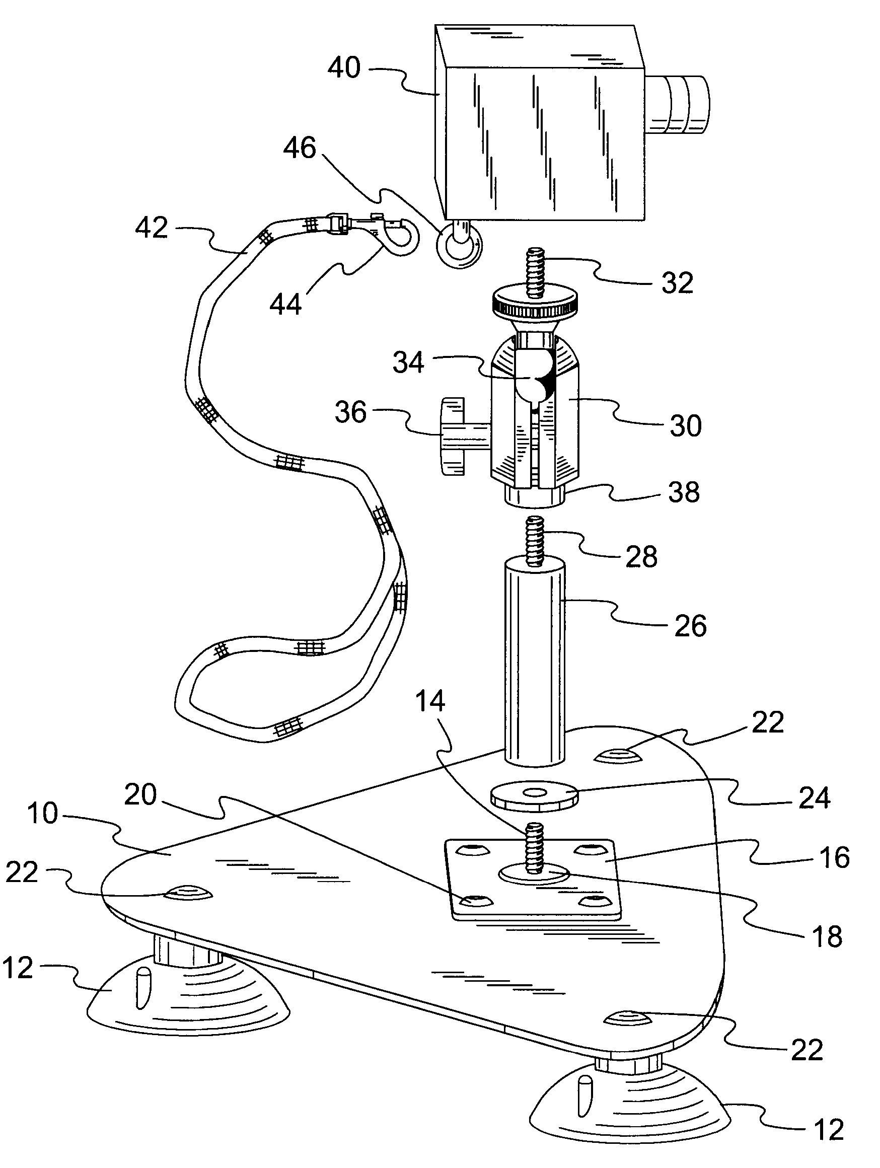
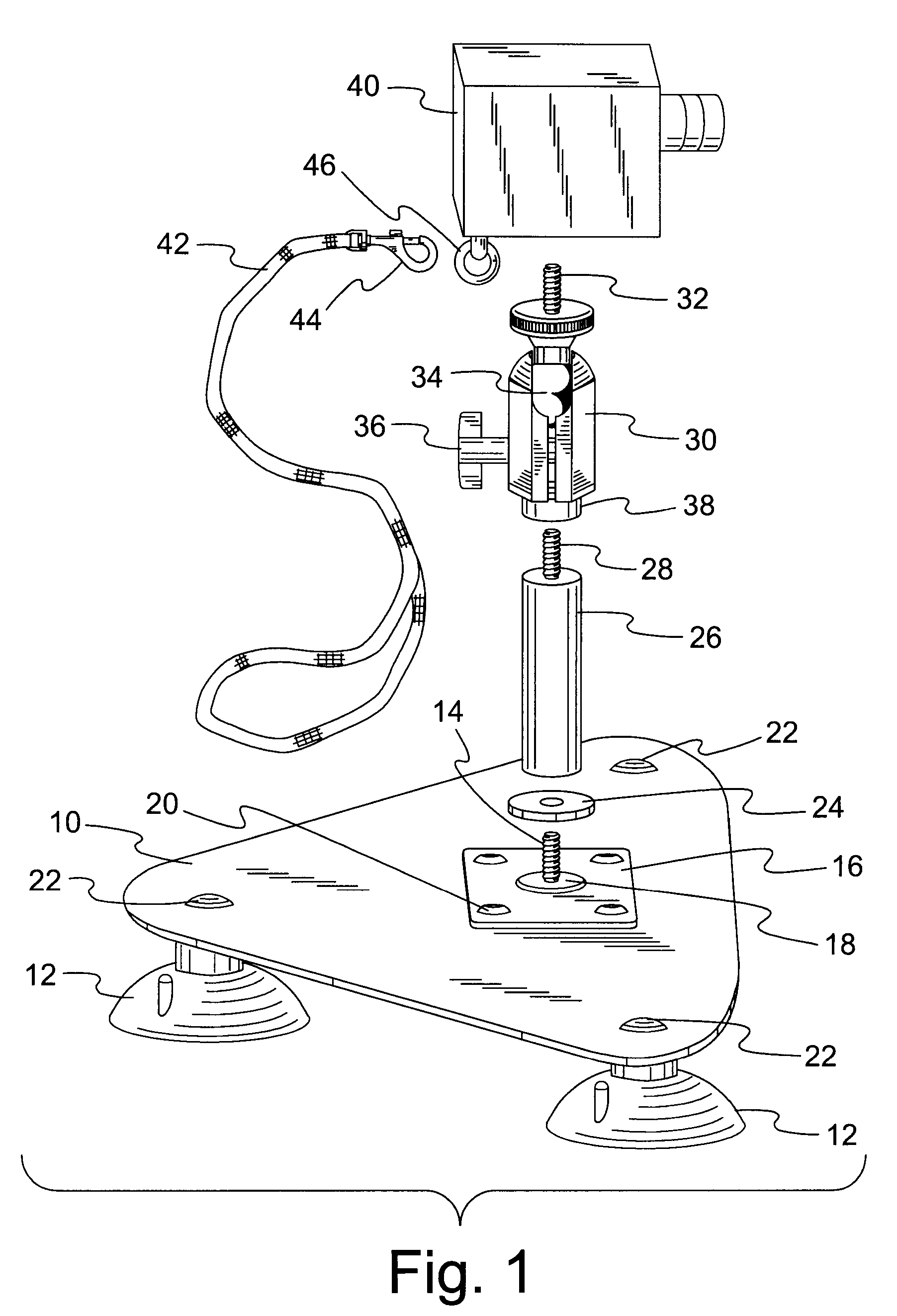
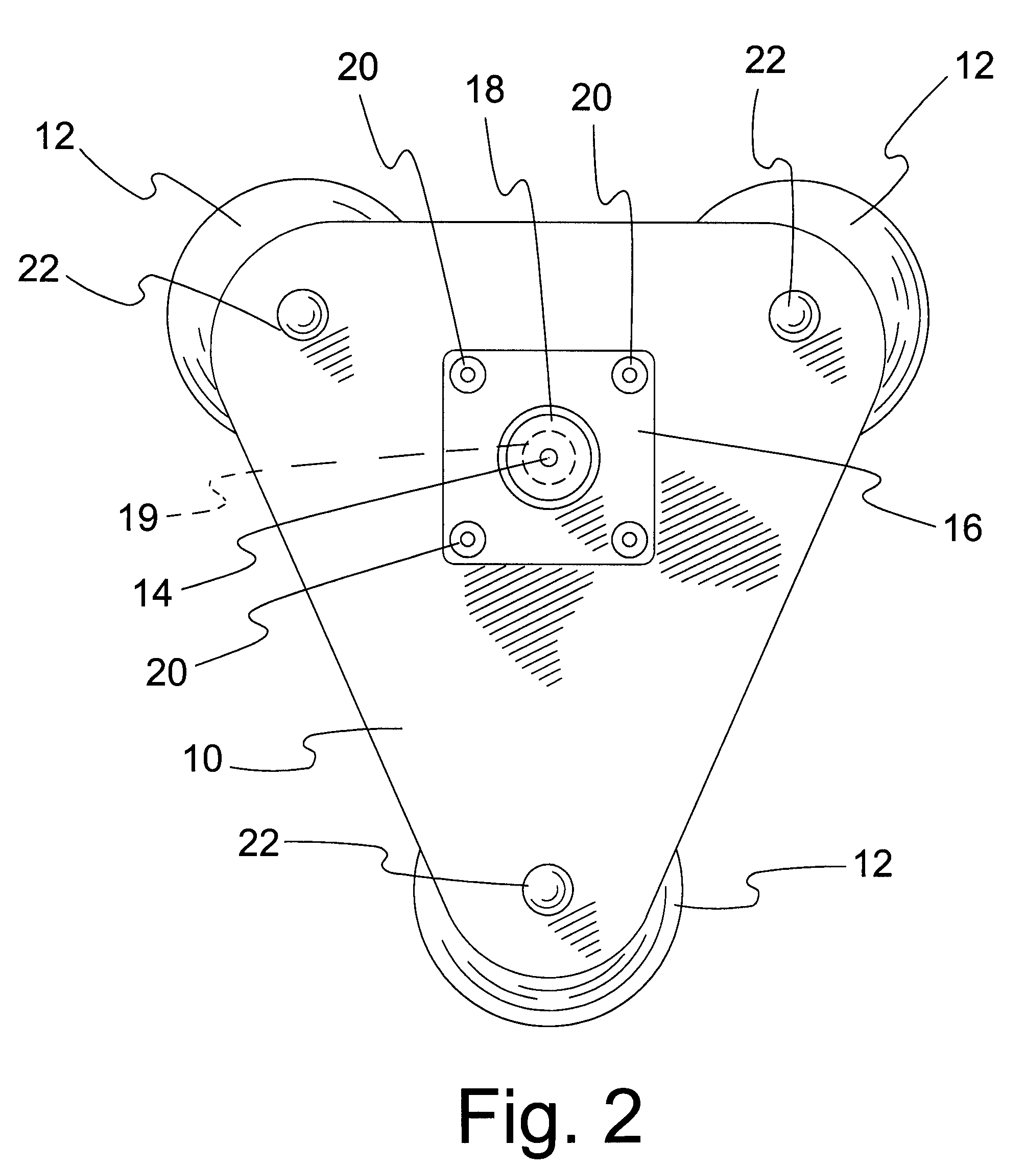
[0027] With reference to FIGS. 1-3, the invention employs a base 10 that is shown as a generally triangular plate. The bottom face of the base 10 carries a plurality of suction cups 12, such as three cups. The cups are located at non-collinear attachment points, with one near each point of the triangle shape. The three suction cups provide three attachment points for mounting the base plate to an external object, thereby establishing a secure and stable mounting plane. The attachment points define corners or vertices of a closed plane geometric figure such as a polygon, or in this case a triangle. The area within the geometric figure is the preferred reception area for mounting a camera. Hence, a camera-mounting stud 14 is located within the area of the geometric figure, preferably near the center of the area.

[0028] The top face of the base 10 carries the camera-mounting stud 14. The stud is located within the geometric figure defined by the plural suction cups. For convenience of a...

second embodiment

[0037]FIGS. 4-6 show the camera mount and provide another camera mount suitable for use in the method of this invention. Similar reference numbers will be used to describe elements in common with the previous embodiment. The base plate 50 is rectangular and provides four corner areas where a suction cup 12 can be suitably attached to the bottom face of the base plate. Carriage bolts 22 provide a suitable means of attachment through the base plate 50. The top face of the base plate 50 carries a camera-mounting stud 14. As previously described, a keeper plate 16 captures the head of the stud 14 under a dome 18. Rivets 20 attach the keeper plate to the base plate 50.

[0038] The rectangular configuration of base plate 50 offers four convenient corner locations for attaching and operating suction cups 12. This configuration is suited for a larger or heavier camera than with the prior embodiment. The presence of four suction cups provides redundant security if one suction cup should fail, ...


PUM


Abstract

A base plate (10, 50) broadly separates suction cups (12) on the bottom face of the base plate for attaching the base plate to a vehicle. A camera-mounting stud (14) extends from the base plate to mount a camera. The keeper plate (16) captures the enlarged head of a camera-mounting stud (14) under a dome (18). Multiple rivets secure the keeper plate to the top face of the base plate, reliably sandwiching the stud head against loss. A camera can be mounted on the threaded shaft of the stud, and the suction cups secure the base plate to a vehicle. Elongated extension rods (26) and swivel rods (30) separate the camera from the base plate. Flexible tethers connected to the camera can restore three-point stability to reduce camera movement while the vehicle is in motion.

Description

BACKGROUND OF INVENTION [0001] 1. Field of the Invention [0002] The invention generally relates to supports and to brackets specially mounted or attached by vacuum, including plural mounted vacuum or suction cups. [0003] 2. Background Art [0004] Photographers employ a number of devices to assist them in obtaining clear pictures under a variety of circumstances. The handheld camera may be the most versatile, because the photographer can support the camera to the best of his ability regardless of ambient conditions. For example, a photographer can take pictures from a moving car while merely holding the camera by hand. Under such conditions, distant shots such as landscapes might be satisfactory, while close shots might be unclear. [0005] A rigid tripod is a common stability aid. If a tripod rests against a steady support, the camera will tend to be steady and produce a clear picture. Tripods are not entirely helpful in a moving car because the car is subject to vibrations and bouncin...

Claims


Application Information

Patent Timeline
Patent Type & Authority Applications(United States)
IPC IPC(8): G03B17/00G03B17/56
CPCB60R11/04B60R2011/004B60R2011/0056G03B17/56F16M11/14F16M11/42F16M13/022B60R2011/0085G03B17/561
Inventor HEIBEL, THOMAS S.
Owner HEIBEL THOMAS S
Why Eureka
Try Eureka