
Lens

a technology for lenses and lenses, applied in the field of lenses for cameras, can solve problems such as image problems, and achieve the effect of reducing the flare phenomenon

Inactive Publication Date: 2019-06-13
SAMSUNG ELECTRO MECHANICS CO LTD
View PDF7 Cites 2 Cited by
  • Summary
  • Abstract
  • Description
  • Claims
  • Application Information

AI Technical Summary

Benefits of technology

The patent describes a lens that can reduce flare, which is a kind of glare caused by light bouncing around in a camera. The lens helps to make pictures or videos look better by minimizing flare.

Problems solved by technology

When an object is imaged by a camera, light incident at an unspecified angle may cause reflections in a lens, and a flare phenomenon, causing problems in an image.

Method used


Image

  • Lens
  • Lens
  • Lens

Examples


Embodiment Construction

[0012]Hereinafter, embodiments of the present disclosure will be described as follows with reference to the attached drawings.

[0013]With respect to terms used in exemplary embodiments, the terms are selected in view of a function of each element, and the terms used in the description are not to be taken in a limiting sense.

[0014]In the exemplary embodiments, when an element is mentioned as being “connected” to another component, this may mean that the element is directly connected to another component, and may also mean that the element is indirectly connected to another component with an intervening element therebetween. Also, it will be understood that when a portion “includes” an element, it may further include another element, not excluding another element, unless otherwise indicated.

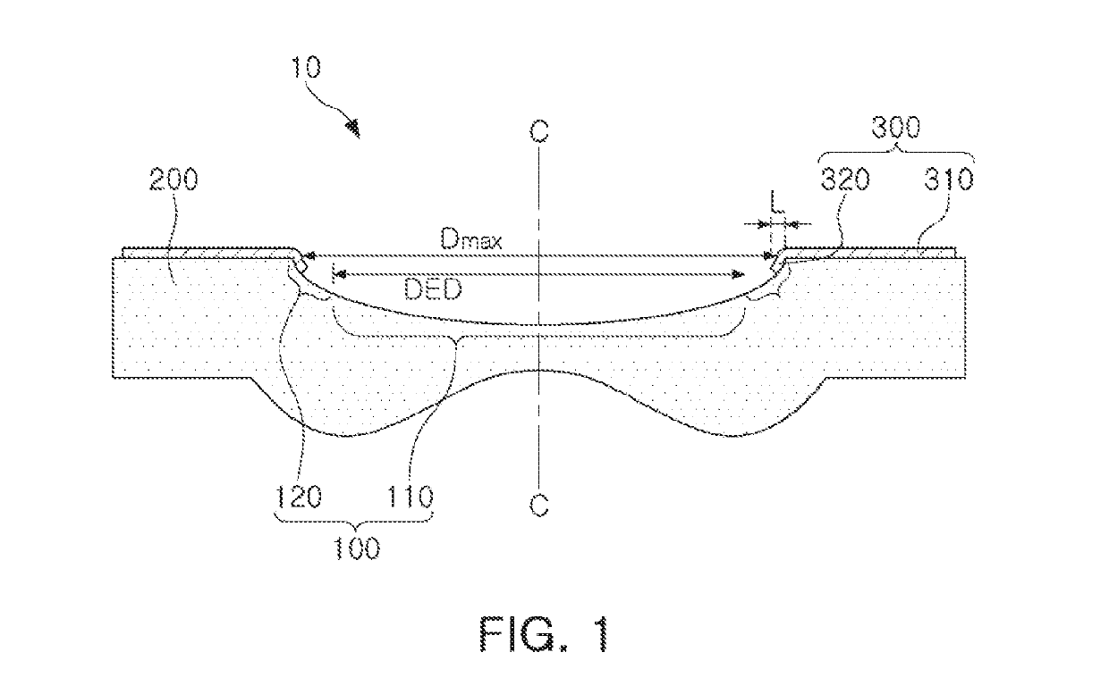
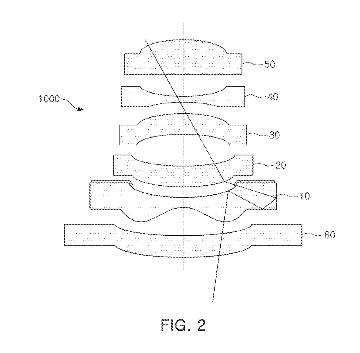
[0015]In the description below, a lens according to an exemplary embodiment will be described with reference to FIG. 1.

[0016]A lens 10 according to the exemplary embodiment may include a refractive ...


PUM


Abstract

A lens includes a refractive portion refracting incident light, a flange portion disposed at an edge of the refractive portion, and a light shielding portion shielding incident light and extending from the flange portion towards the refractive portion.

Description

CROSS-REFERENCE TO RELATED APPLICATION(S)[0001]This application claims benefit of priority to Korean Patent Application No. 10-2017-0170635 filed on Dec. 12, 2017 in the Korean Intellectual Property Office, the disclosure of which is incorporated herein by reference in its entirety.BACKGROUND1. Field[0002]The present disclosure relates to a lens for a camera configured to reduce a flare phenomenon.2. Description of Related Art[0003]When an object is imaged by a camera, light incident at an unspecified angle may cause reflections in a lens, and a flare phenomenon, causing problems in an image. A flare phenomenon may be reduced using an aperture disposed between lenses, but a flare phenomenon may not be completely removed. Also, an aperture may significantly reduce the amount of light incident through a lens, which may lead to reduction in relative illumination (RI).[0004]Thus, it may be necessary to develop a lens which can reduce a flare phenomenon without reducing relative illumina...

Claims


Application Information

Patent Timeline
Patent Type & Authority Applications(United States)
IPC IPC(8): G02B13/18G02B7/02
CPCG02B13/18G02B27/0018G02B5/005G02B13/0045G02B3/0087G02B3/02G02B7/02
Inventor KIMSHIN, MAN SUBJIN, YOUNG SUYOO, JUN HWANKIM, IN GUN
Owner SAMSUNG ELECTRO MECHANICS CO LTD
Learn More