Electric motor having electric conductors spaced apart from stator slots

a technology of electric conductors and stator slots, which is applied in the direction of dynamo-electric machines, electrical apparatus, magnetic circuits, etc., can solve the problems of increasing the pressure loss of pumping coolant, unable to guarantee uniform flow, and damaging each other or the insulating layer in the slots, so as to improve the insulating effect and reduce wear resistance. , the effect of excellent insulating

Inactive Publication Date: 2020-01-09
DR ING H C F PORSCHE AG
View PDF0 Cites 4 Cited by
  • Summary
  • Abstract
  • Description
  • Claims
  • Application Information

AI Technical Summary

Benefits of technology

[0016]According to another preferred embodiment of the invention, it is envisaged that the positioning disks are manufactured from a ceramic material. Corresponding ceramic materials are robust, excellent insulators and heat resistant.
[0017]According to another preferred embodiment of the invention, it is envisaged that the positioning disks are manufactur...

Problems solved by technology

However, there are significant disadvantages with this.
Owing to relative movements caused, for example, by the flowing coolant, they can damage each other or the insulating layer in the slots.
Moreover, the flow geometry within the slots is undefined and stagnant areas arise in which the coolant does not flow but is stationary, the conductors are not always completely wetted and the pre...

Method used


Image

  • Electric motor having electric conductors spaced apart from stator slots
  • Electric motor having electric conductors spaced apart from stator slots

Examples


Embodiment Construction

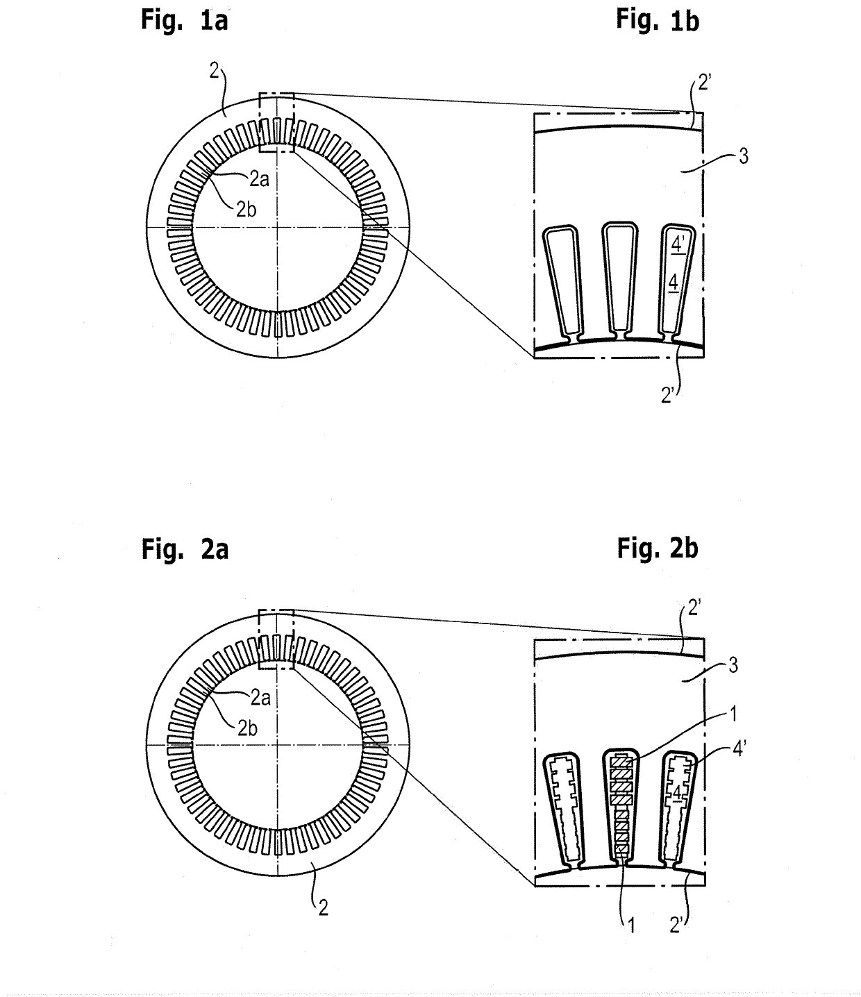
[0035]FIGS. 1a and 1b illustrate schematically the stator lamination 2 and the positioning disk 3 according to one illustrative embodiment of the present invention. FIG. 1a shows the stator lamination 2. When the stator laminations 2 are joined together to form a stator lamination stack, radial teeth 2a and radial interspaces 2b between the teeth 2a form the slots of the stator lamination stack.

[0036]FIG. 1b shows a segment of the positioning disk 3. The geometric shape of the positioning disk 3 corresponds very largely to the geometric shape of the stator lamination 2, illustrated here is an outline of the stator lamination 2′. The positioning disk 3 is produced from a plastic. The leadthroughs 4 of the positioning disk 3 are arranged in a manner centered relative to the interspaces 2b of the stator lamination 2. The extents of the leadthroughs 4 are less than the extents of the interspaces 2b, and therefore parts of the positioning disk 3 project into the slots of the stator lamin...


PUM


Abstract

An electric motor includes a stator having a stator lamination stack and electric conductors. The stator lamination stack has a plurality of stator laminations, wherein the stator lamination stack has axial slots. The stator lamination stack has a plurality of positioning disks, and the positioning disks have leadthroughs. The electric conductors are arranged in the slots, being passed through the leadthroughs, wherein the leadthroughs have positioning regions for positioning the electric conductors. Also described is a method for operating an electric motor and a method for producing an electric motor.

Description

CROSS-REFERENCE TO RELATED APPLICATION[0001]This application claims priority to German Patent application No. DE 10 2018 116 031.3, filed Jul. 3, 2018, which is incorporated by reference herein in its entirety.FIELD OF THE INVENTION[0002]The present invention relates to an electric motor, in particular to a permanently excited synchronous machine as an internal rotor motor, preferably for use in motor vehicles. The present invention furthermore relates to a method for operating an electric motor and to a method for producing an electric motor.BACKGROUND OF THE INVENTION[0003]Electric motors in motor vehicles generally have a stator and a rotor. Here, the stator has a stator lamination stack, which essentially comprises adjacently arranged stator laminations of the same geometry. The stator lamination stack reduces eddy current losses due to electric conductors laid in slots of the stator lamination stack.[0004]The electric conductors must be insulated relative to the stator laminati...

Claims


Application Information

Patent Timeline
IPC IPC(8): H02K3/24H02K1/04H02K1/16H02K9/197
CPCH02K3/24H02K9/197H02K1/04H02K1/16H02K1/185H02K3/12H02K3/345
Inventor OECHSLEN, STEFANSTOLL, JOHANNESBERENDES, PHILIPPSCHNEIDER, JÖRGMERATH, WOLFGANGBODENMILLER, DANIELTHALER, WOLFGANG
Owner DR ING H C F PORSCHE AG
Why Eureka
Try Eureka