Assembling structure for a conductive plate of a handheld power tool

a technology of conductive plates and assembly structures, applied in the field of tools, can solve the problems of increased cost, extra welding process, extra cost in consumables, etc., and achieve the effect of reducing the cost of manufacturing and maintenan

Active Publication Date: 2020-07-23
LIN YU TANG
View PDF0 Cites 1 Cited by
  • Summary
  • Abstract
  • Description
  • Claims
  • Application Information

AI Technical Summary

Benefits of technology

[0010]The main objective of the present invention is to provide an assembling structure for a conductive plate of a handheld power ...

Problems solved by technology

First, the manufacturer has to do an extra welding process after assembling so that the cost will increase.
In other words, the extra welding process leads to extra cost in consumables, and the welding process, no matter done manually by labor or automatically on an assembly line, takes extra time...

Method used


Image

  • Assembling structure for a conductive plate of a handheld power tool
  • Assembling structure for a conductive plate of a handheld power tool
  • Assembling structure for a conductive plate of a handheld power tool

Examples


Embodiment Construction

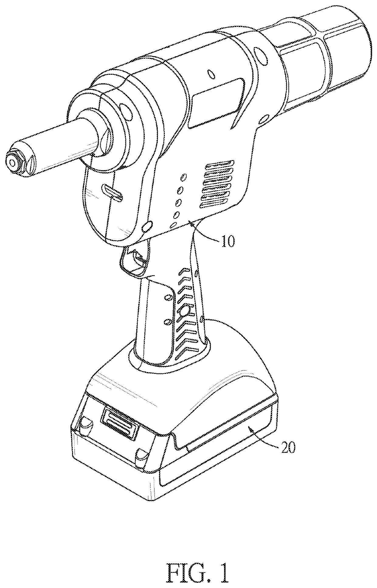
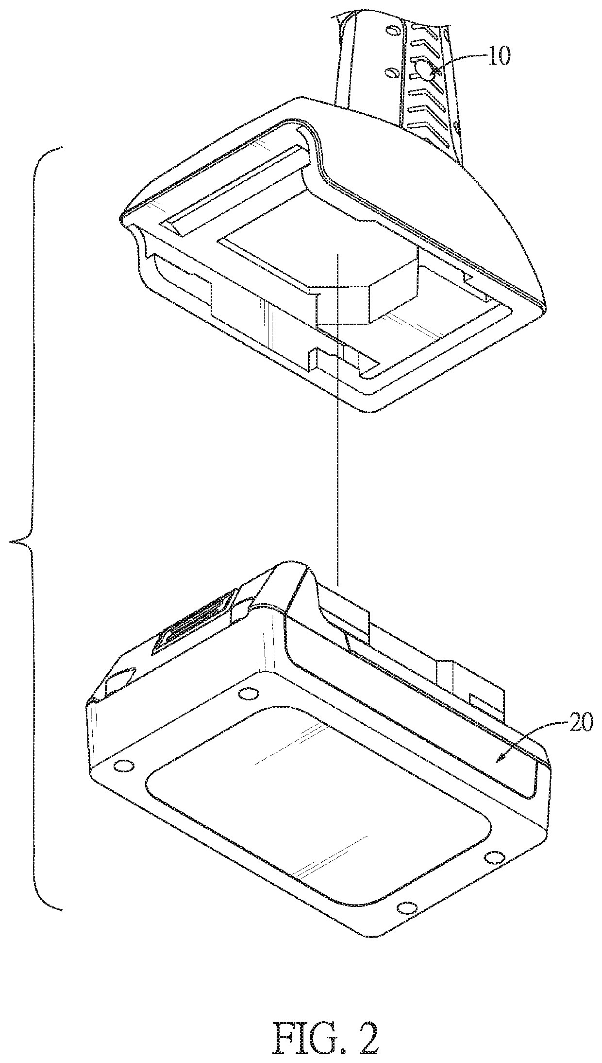
[0021]With reference to FIGS. 1 and 2, an assembling structure for a conductive plate of a handheld power tool in accordance with the present invention comprises a handheld seat 10 and a battery 20.

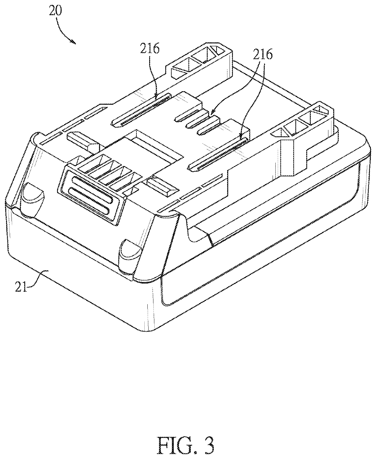
[0022]With further reference to FIGS. 3 and 4, the battery 20 is mounted on a bottom end of the handheld seat 10 and has a casing 21, a circuit board 25, an adapter 26, and multiple conductive plates 27.

[0023]With further reference to FIGS. 4, 5 and 6, the casing 21 has an inner space 215 and multiple conducting holes 216. The circuit board 25 is located in the inner space 215 of the casing 21.

[0024]The adapter 26 is located in the inner space 215 of the casing 21, is mounted on a top surface of the circuit board 25, and has multiple adapting grooves 261. Specifically, in this embodiment, the adapter 26 is detachably mounted on the top surface of the circuit board 25. More specifically, the adapter 26 has multiple combining pillars 262 formed on a bottom surface of the adapter 26 and the ...


PUM


Abstract

An assembling structure for a conductive plate of a handheld power tool has a battery having a casing, a circuit board, an adapter, and multiple conductive plates. The circuit board, the adapter and the conductive plates are all located in the casing. The adapter is mounted on a top surface of the circuit board, and has multiple adapting grooves. The conductive plates are mounted in the adapting grooves of the adapter respectively, and are electrically connected to the circuit board. By mounting the adapter on the top surface of the circuit board and mounting the conductive plates in the adapting grooves of the adapter respectively, the conductive plates and the circuit board are able to be combined and fixed together by the adapter without the welding progress, which reduces the consumable cost, the labor cost, and the time consumption.

Description

CROSS-REFERENCE TO RELATED APPLICATIONS[0001]This application is based upon and claims priority under 35 U.S.C. 119 from Taiwan Patent Application No. 108201032 filed on Jan. 22, 2019, which is hereby specifically incorporated herein by this reference thereto.BACKGROUND OF THE INVENTION1. Field of the Invention[0002]The present invention relates to a tool, especially to a handheld power tool.2. Description of the Prior Arts[0003]A handheld power tool makes assembling or disassembling of objects easier and more effective. The handheld power tool uses a battery as a power source and is combined with a traditional hand tool such as a screwdriver or a drill so that people can use a handheld power tool instead of manually driving the hand tools.[0004]The abovementioned handheld power tool has a driving assembly, a handheld seat, and a battery. The battery is detachably mounted on a bottom end of the handheld seat as a power source to drive the driving assembly which is mounted on a top e...

Claims


Application Information

Patent Timeline
IPC IPC(8): H01R31/06H01M10/42H01M2/20B25F5/02H01M50/296H01M50/50
CPCH01M10/425H01R31/06H01M2220/30B25F5/02H01M2/20B25B21/00H01M2010/4271Y02E60/10H01M50/50H01M50/296H01M10/42
Inventor LIN, YU-TANGKAO, HSIEN-YU
Owner LIN YU TANG
Why Eureka
Try Eureka