Manufacturing method for slinger used in rotary seal, and rotary seal

a manufacturing method and technology of slinger, applied in the field of slinger, can solve the problems of unfavorable additional manufacturing cost of performing the step, and achieve the effects of reducing production costs, reducing production costs, and reducing production costs

Active Publication Date: 2020-07-30
NAKANISHI METAL WORKS CO LTD
View PDF2 Cites 0 Cited by
  • Summary
  • Abstract
  • Description
  • Claims
  • Application Information

AI Technical Summary

Benefits of technology

[0050](1) The annular blank material is molded from the dull-finished steel sheet material, and the annular blank material is burred (claim 1) or the annular blank material is burred and pressed (claim 2), whereby the surface roughness of each of the first slide-contact surface and the second slide-contact surface of the slinger can be set to fall within the predetermined range (0.25 μm≤Ra≤0.5 μm). Accordingly, the slinger used in the rotary seal can be inexpensively and efficiently manufactured.
[0051](2) In a particular method of the present invention, the annular blank material is molded from the dull-finished steel sheet material and the annular blank material is burred. Accordingly, the surface roughness of each of the slide-contact surfaces of the slinger falls within the predetermined range (claim 1), the surface roughness of each of the first slide-contact surface and the second slide-contact surface of the slinger can be set to fall within the predetermined range through the burring. Accordingly, the separate step such as the pressing step becomes unnecessary, and thus the slinger can be further inexpensively manufactured.
[0052](3) The predetermined range is a range that is determined based on experiments by the inventors of the present application. If the surface roughness of each of the first slide-contact surface and the second slide-contact surface of the slinger is set to fall within the predetermined range, it is possible to make the wear amount of each of the axial lip and the radial lip small while the oil film retainability is ensured.
[0053]In the slinger manufactured through the manufacturing method according to the present invention, the surface roughness of each of the first slide-contact surface with which the axial lip is in slidable contact and the second slide-contact surface with which the radial lip is in slidable contact, is within the predetermined range. Accordingly, in the rotary seal using the slinger, the wear amount of each of the axial lip and the radial lip can be reduced while the oil film retainability is ensured.

Problems solved by technology

When a slide-contact surface of a slinger is formed as an uneven surface through another step separate from press working for molding the slinger, such as a step of fine-rigid particle impact, cutting processing, wet blasting, or shot peening, an additional manufacturing cost for performing the step is unfortunately required.

Method used


Image

  • Manufacturing method for slinger used in rotary seal, and rotary seal
  • Manufacturing method for slinger used in rotary seal, and rotary seal
  • Manufacturing method for slinger used in rotary seal, and rotary seal

Examples


Embodiment Construction

[0062]Hereinafter, an embodiment of the present invention will be described in detail with reference to the accompanying drawings.

[0063]As used herein, in a state where a rotary seal is mounted to a bearing device for supporting a wheel of an automobile, the direction of the rotation axis of the bearing device is referred to as “axial direction”, and a direction perpendicular to the axial direction is referred to as “radial direction”.

[0064]In addition, a direction from a vehicle body of the automobile toward the wheel side is referred to as “outboard”, and the direction opposite thereto is referred to as “inboard”.

[0065]

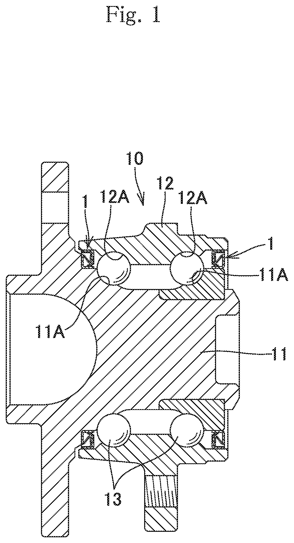
[0066]A vertical sectional view in FIG. 1 schematically shows a part of the example in which rotary seals 1 according to the embodiment of the present invention are used in a bearing device 10 for supporting a wheel of an automobile.

[0067]The bearing device 10 includes a bearing including: an inner ring 11 which has an inner ring raceway surface 11A formed on the ou...


PUM

PropertyMeasurementUnit
arithmetical mean roughness Raaaaaaaaaaa
arithmetical mean roughnessaaaaaaaaaa

Abstract

A manufacturing method of a slinger, includes steps of: molding an annular blank material from a dull-finished steel sheet material through sheet metal press working or the like; and burring the blank material to mold a slinger. The values of the arithmetical mean roughness Ra of faces, of a burring mold, which individually come into contact with first and second slide-contact surfaces of the slinger, are set to 0.03 μm≤Ra≤0.07 μm. A ratio of pressure application force for holding the blank material between the faces to the 0.2% proof stress of the dull-finished material, is set to 1.0 or more and 1.53 or less. A clearance for the burring mold is set to T×(0.9 to 0.7) where “T” represents the sheet thickness of the blank material.

Description

BACKGROUND OF THE INVENTIONField of the Invention[0001]The present invention relates to a manufacturing method for a slinger used in a rotary seal including the slinger, a core metal, and a seal member.Description of the Background Art[0002]There have been rotary seals including a slinger, a core metal, and a seal member, as rotary seals used in bearing devices for supporting wheels of automobiles and other bearing devices (see, for example, Patent Literatures 1 to 3).[0003]Here, the slinger includes a cylindrical sleeve and a flange extending outward in the radial direction from one end of the sleeve in the axial direction.[0004]The core metal includes a core metal cylinder having a cylindrical shape, and a core metal flange extending inward in the radial direction from one end of the core metal cylinder in the axial direction.[0005]The seal member includes a base portion joined to the core metal, and a seal lip portion extending from the base portion.[0006]Such a rotary seal is us...

Claims


Application Information

Patent Timeline
Patent Type & Authority Applications(United States)
IPC IPC(8): F16C43/04F16C33/78
CPCF16C33/782F16C43/045F16C2220/02F16C33/783F16C33/7806F16C33/7823F16C33/7889F16J15/3232F16J15/3252B60B27/0073B23P15/00F16C2326/02F16C2240/54F16C2204/60F16C2220/40F16C2220/60F16C2220/82F16C2240/60F16C2240/46B21D19/088B21D53/10B21D53/20F16C33/7883F16C33/7826F16C2220/42F16C19/186
Inventor SHIMADA, WATARUAKASHI, SHINICHIIIZAWA, YUSUKE
Owner NAKANISHI METAL WORKS CO LTD
Why Eureka
Try Eureka