Method and device in communication node used for wireless communication

Active Publication Date: 2020-10-01
SHANGHAI LANGBO COMM TECH CO LTD
View PDF0 Cites 3 Cited by
  • Summary
  • Abstract
  • Description
  • Claims
  • Application Information

AI Technical Summary

Benefits of technology

The patent text describes a method for adjusting the timing of uplink transmissions in Non-Terrestrial Networks (NTN) using a two-stage approach. The first stage adjusts the timing to ensure coarse synchronization, while the second stage adjusts the timing to ensure fine synchronization within the scope of the cyclic prefix. This method reduces the complexity of the timing adjustment and allows for flexible base station scheduling. It also allows for the notification and fine-tuning of the reference timing, reducing signaling overhead and maintaining the existing design in 5G NR.

Problems solved by technology

In addition, when a satellite is used as a relay equipment of a terrestrial base station, a delay in a Feeder Link between the satellite and the terrestrial base station will further increase transmission delay between a UE and a base station.

Method used


Image

  • Method and device in communication node used for wireless communication
  • Method and device in communication node used for wireless communication
  • Method and device in communication node used for wireless communication

Examples


embodiment 1

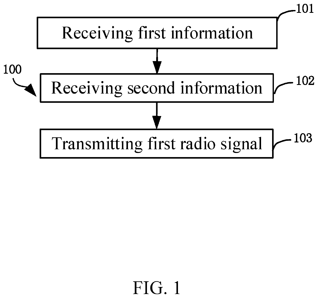
[0095]Embodiment 1 illustrates a flowchart of transmission of first information, second information, and a first radio signal according to one embodiment of the present disclosure, as shown in FIG. 1. In FIG. 1, each box represents a step. In Embodiment 1, the first-type communication node in the present disclosure first receives first information, then receives second information, and then transmits a first radio signal; wherein the first information is used to determine a first transmission timing adjustment, the second information is used to determine a second transmission timing adjustment, and a start time for a transmission of the first radio signal is related to the first transmission timing adjustment and the second transmission timing adjustment; a minimum step-size corresponding to the first transmission timing adjustment is not equal to a minimum step-size corresponding to the second transmission timing adjustment; the first information, the second information and the fir...

embodiment 2

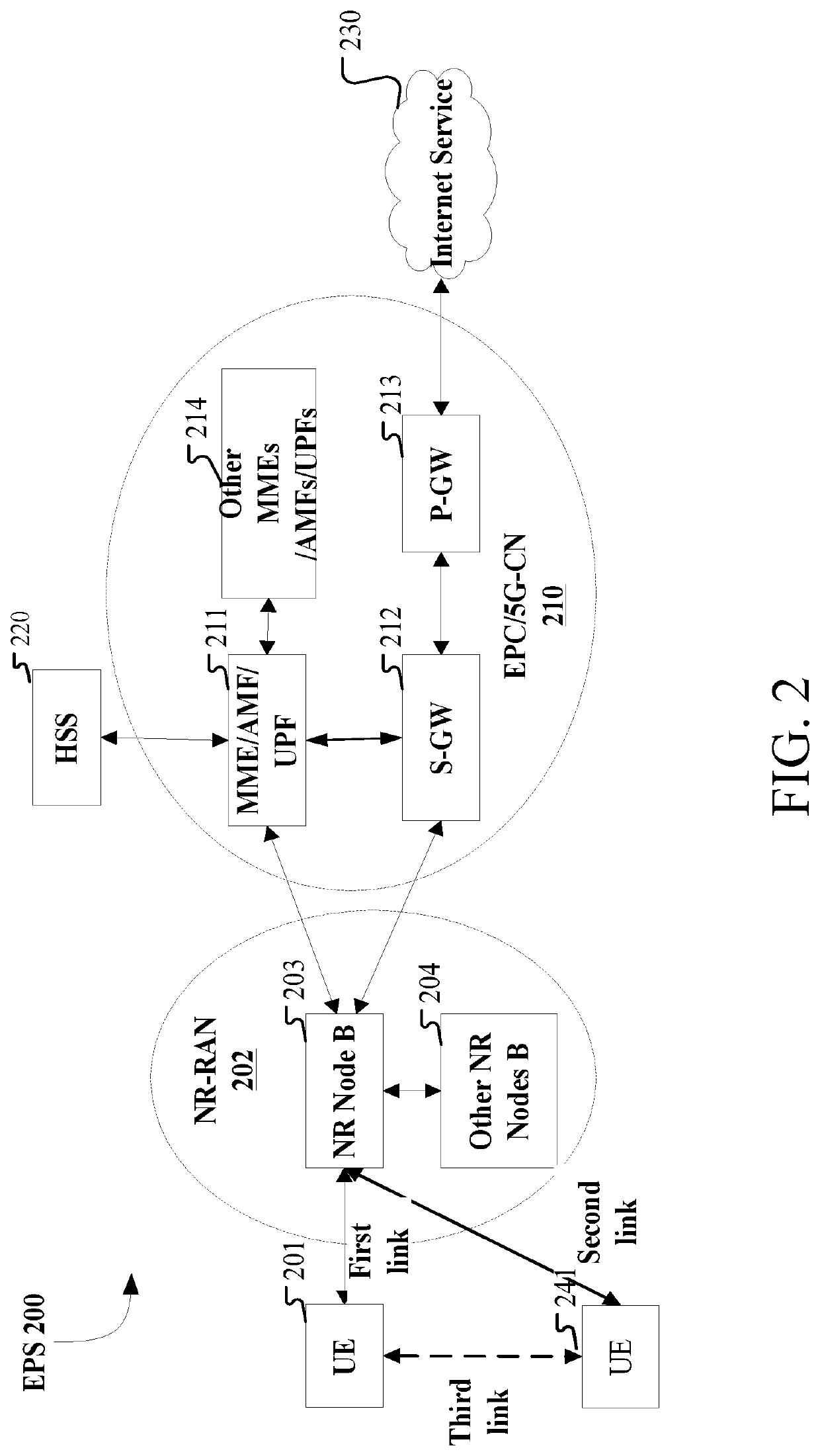
[0170]Embodiment 2 illustrates a schematic diagram of a network architecture according to the present disclosure, as shown in FIG. 2. FIG. 2 illustrates the network architecture 200 of NR 5G, Long-Term Evolution (LTE) and Long-Term Evolution Advanced (LTE-A). The NR 5G or LTE network architecture 200 may be called an Evolved Packet System (EPS) 200. The EPS 200 may comprise one or more UEs 201, an NG-RAN 202, an Evolved Packet Core / 5G-Core Network (EPC / 5G-CN) 210, a Home Subscriber Server (HSS) 220 and an Internet Service 230. The EPS 200 may be interconnected with other access networks. For simple description, the entities / interfaces are not shown. As shown in FIG. 2, the EPS provides packet switching services. Those skilled in the art will find it easy to understand that various concepts presented throughout the present disclosure can be extended to networks providing circuit switching services or other cellular networks. The NG-RAN comprises an NR node B (gNB) 203 and other gNBs ...

embodiment 3

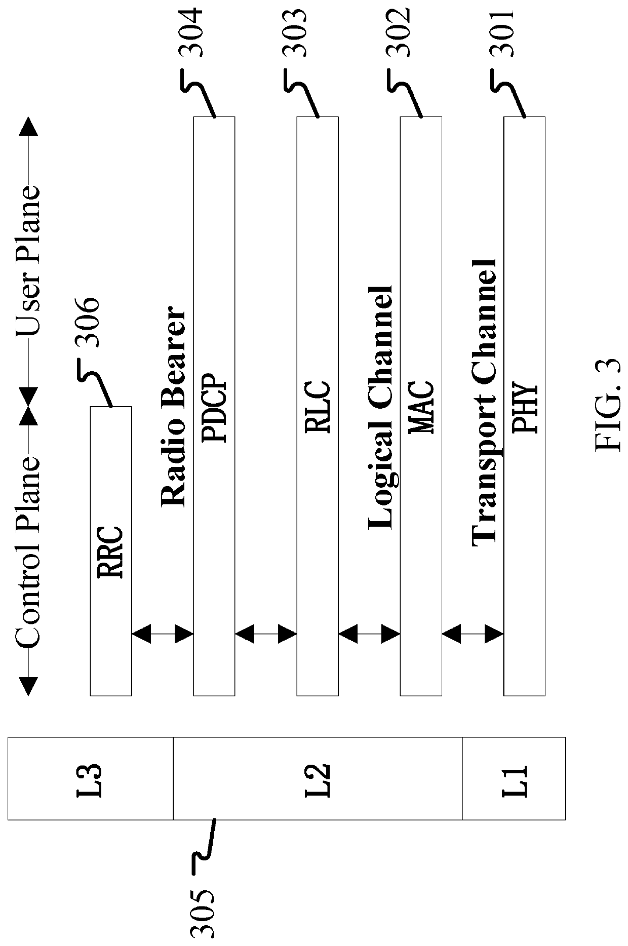
[0175]Embodiment 3 illustrates a schematic diagram of an example of a radio protocol architecture of a user plane and a control plane according to one embodiment of the present disclosure, as shown in FIG. 3. FIG. 3 is a schematic diagram illustrating an embodiment of a radio protocol architecture of a user plane and a control plane. In FIG. 3, the radio protocol architecture for a first-type communication node (UE) and a second-type communication node (gNB, eNB or a satellite in NTN) is represented by three layers, which are a layer 1, a layer 2 and a layer 3, respectively. The layer 1 (L1) is the lowest layer and performs signal processing functions of various PHY layers. The L1 is called PHY 301 in the present disclosure. The layer 2 (L2) 305 is above the PHY 301, and is in charge of the link between a first-type communication node and a second-type communication node via the PHY 301. In the user plane, L2 305 comprises a Medium Access Control (MAC) sublayer 302, a Radio Link Con...


PUM


Abstract

The present disclosure provides a method and a device in a communication node for wireless communications. The communication node in the present disclosure first receives first information, then receives second information, and then transmits a first radio signal; wherein the first information is used to determine a first transmission timing adjustment, the second information is used to determine a second transmission timing adjustment, and a start time for a transmission of the first radio signal is related to the first transmission timing adjustment and the second transmission timing adjustment; a minimum step-size size corresponding to the first transmission timing adjustment is not equal to a minimum step-size size corresponding to the second transmission timing adjustment; the first information, the second information and the first radio signal are all transmitted through an air interface. The disclosure can support large-delay-transmission and reduce overhead for configuring signaling of Time Advance (TA).

Description

CROSS REFERENCE TO RELATED APPLICATIONS[0001]This application is a continuation of International Application No. PCT / CN2017 / 114829, filed on Dec. 6, 2017, claiming the priority benefit of International Application PCT / CN2017 / 114829, filed on Dec. 6, 2017, the full disclosure of which is incorporated herein by reference.BACKGROUNDTechnical Field[0002]The present disclosure relates to a transmission method and device in a wireless communication system and in particular to a transmission scheme and device in non-terrestrial wireless communications.Related Art[0003]The disclosure scenarios of wireless communication systems will become increasingly diverse in the future, and different disclosure scenarios put forward different performance requirements on the system. In order to meet the different performance requirements of various application scenarios, the research on New Radio (NR), or what is called Fifth Generation (5G), is decided to be conducted at the 3rd Generation Partner Proje...

Claims


Application Information

Patent Timeline
IPC IPC(8): H04W56/00H04L1/00
CPCH04L1/0029H04W56/0045H04W92/10H04W56/00H04W84/06H04L5/0053
Inventor LIU, ZHENGZHANG, XIAOBO
Owner SHANGHAI LANGBO COMM TECH CO LTD
Why Eureka
Try Eureka