Method for activating recordings of events concerning terminals and equipment thereof

Inactive Publication Date: 2010-01-12
ALCATEL LUCENT SAS
View PDF10 Cites 3 Cited by
  • Summary
  • Abstract
  • Description
  • Claims
  • Application Information

AI Technical Summary

Benefits of technology

[0021]Such a mode of operation ensures the flexibility of a local activation of the trace, via the operation center, which may be an OMC, or even a supervisory unit co-located with a radio network controller. It also enables the management of the trace activation instruction to be left to the core network. Furthermore, it allows for local activation of the trace in the radio network controller while avoiding systematically providing the latter with the terminal identifier for each call.

Problems solved by technology

Now, the main players in the field concerned consider the systematic presence of such an identifier within the RNC to be totally undesirable for various reasons.
Such a mechanism would then result in a signaling overload prejudicial to the system.

Method used


Image

  • Method for activating recordings of events concerning terminals and equipment thereof
  • Method for activating recordings of events concerning terminals and equipment thereof

Examples


Embodiment Construction

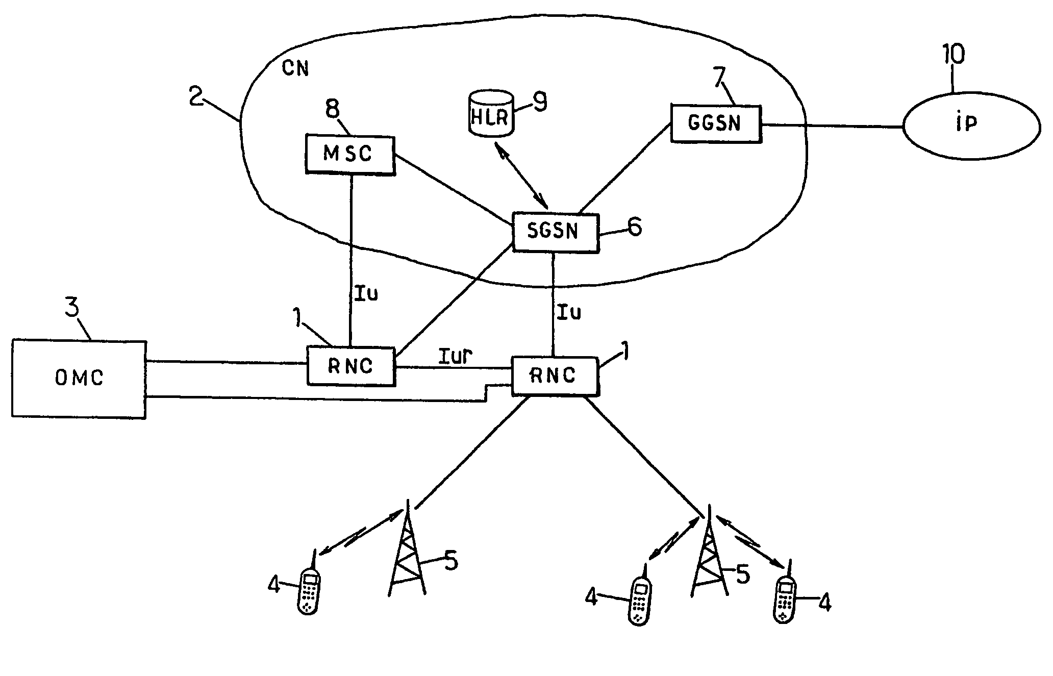
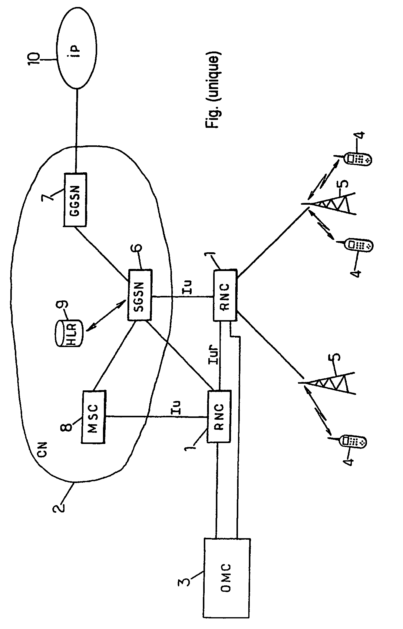
[0025]The FIGURE shows a radiocommunication system including RNCs 1, a core network CN 2 and an OMC 3, in accordance with the normal definitions of these component elements of a UMTS network summarized in the introduction.

[0026]The CN 2 includes a meshed arrangement of switches suitable for transmitting speech traffic in circuit mode such as the MSC (Mobile service Switching Center) 8 or data traffic in packet mode such as the SGSN (Serving GPRS Support Node) 6, GPRS standing for “General Packet Radio Service”. The switches are conventionally linked to each other and / or to a particular switch used as a platform towards an external network, such as, for example, the GGSN (Gateway GPRS Support Node) 7 which is interconnected with an IP (Internet Protocol) type data network 10 in the example illustrated in the FIGURE.

[0027]The RNCs 1 are linked to the CN 2, via a switch of the CN, for example an SGSN 6 or an MSC 8. The standardized interface that links these elements is the Iu interfac...


PUM


Abstract

The invention concerns a method which consists, in a radio communication system comprising a core network, at least one radio network controller connected to the core network and configured to control radio communications with terminals and at least one operation center capable of supervising said radio network controller, in: transmitting from the operating center to a radio network controller, a coded list of terminal identifiers; transmitting the coded list to the control network from the radio network controller; decoding the coded list at the core network; detecting at the core network a radio communication under the control of the radio network controller, with a terminal identified in the decoded list; and instructing the radio network controller, from the core network, to start a recording of events concerning the detected communication.

Description

[0001]This is the U.S. National Phase of International Application No. PCT / FR2004 / 001095 filed 6 May 2004, the entire disclosure of which is incorporated herein by reference.BACKGROUND OF THE INVENTION[0002]The present invention relates to recordings of events concerning the terminals in a radiocommunication system. It relates more particularly to the method of activating such recordings.[0003]The recording of certain events that can occur in a call or an exchange of information with a terminal is a routine operation in radiocommunication systems. The duly stored events are normally signaling messages, typically of level 3, interchanged between the terminal and the radiocommunication system. Such an operation is known by the term “trace”.[0004]The trace is performed on one or more nodes of the radiocommunication system and can be used by the operator of this system for subsequent processing purposes (statistical analysis of calls in a geographic area, study of the behavior of a part...

Claims


Application Information

Patent Timeline
IPC IPC(8): H04W4/00H04W24/08
CPCH04W24/08
Inventor FAUCONNIER, DENISSEHEDIC, YANN
Owner ALCATEL LUCENT SAS
Why Eureka
Try Eureka