Surge protection device

Active Publication Date: 2020-02-06
PHOENIX CONTACT GMBH & CO KG
View PDF4 Cites 5 Cited by
  • Summary
  • Abstract
  • Description
  • Claims
  • Application Information

AI Technical Summary

Benefits of technology

[0007]The object of the invention is to provide a surge protection device which, in addition to a compact, stable

Problems solved by technology

It is disadvantageous in the known arrangement that tensile forces that arise in the case of overvoltage have to be taken up by the housing, which results in twisting.
Moreo

Method used


Image

  • Surge protection device
  • Surge protection device
  • Surge protection device

Examples


Example

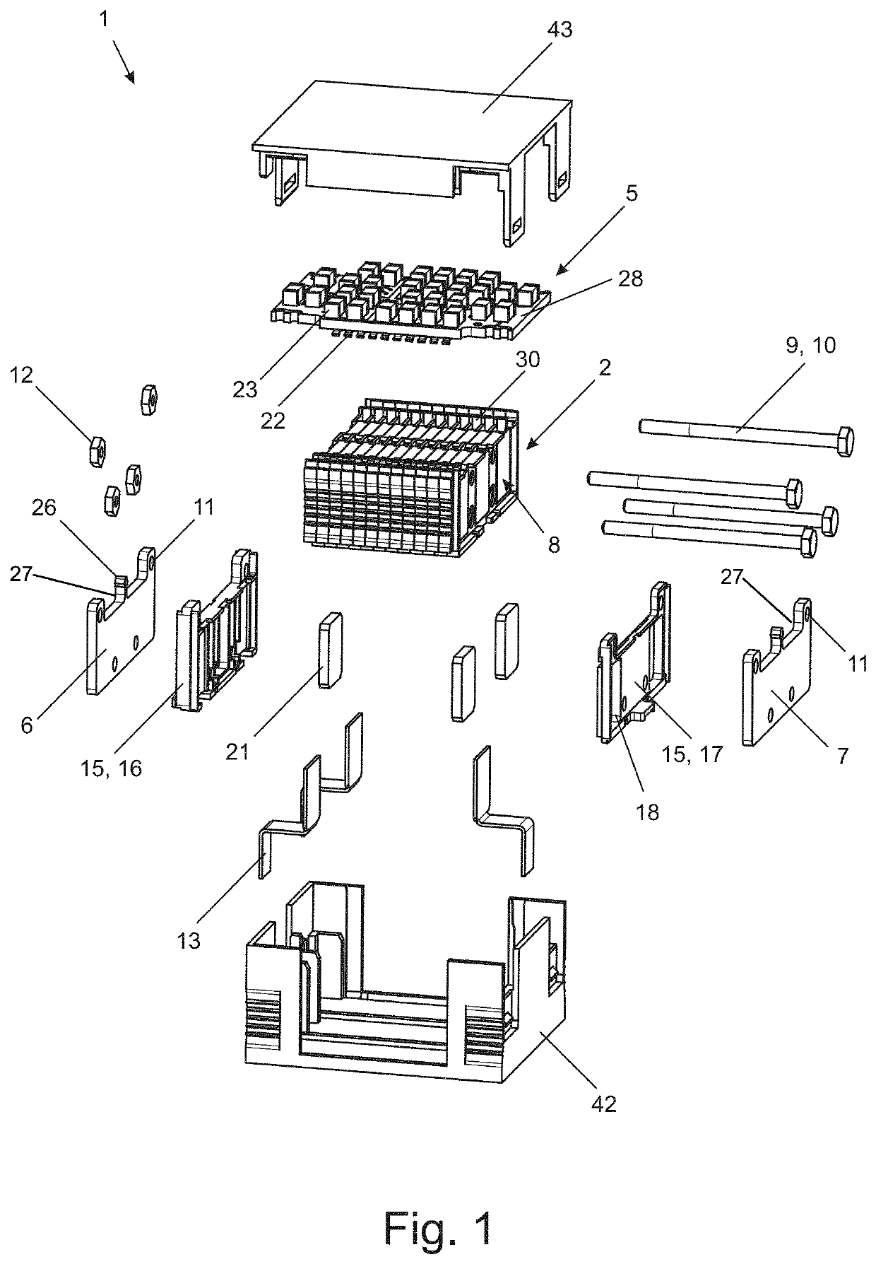
[0034]In the figures, a surge protection device 1 or individual components of a surge protection device 1 is / are depicted as a whole. In the case of the surge protection device 1, the surge diverters are produced by stack spark gaps 2. The individual stack spark gaps 2 are comprised of multiple electrodes 3, between which respective insulating elements 4 are arranged.

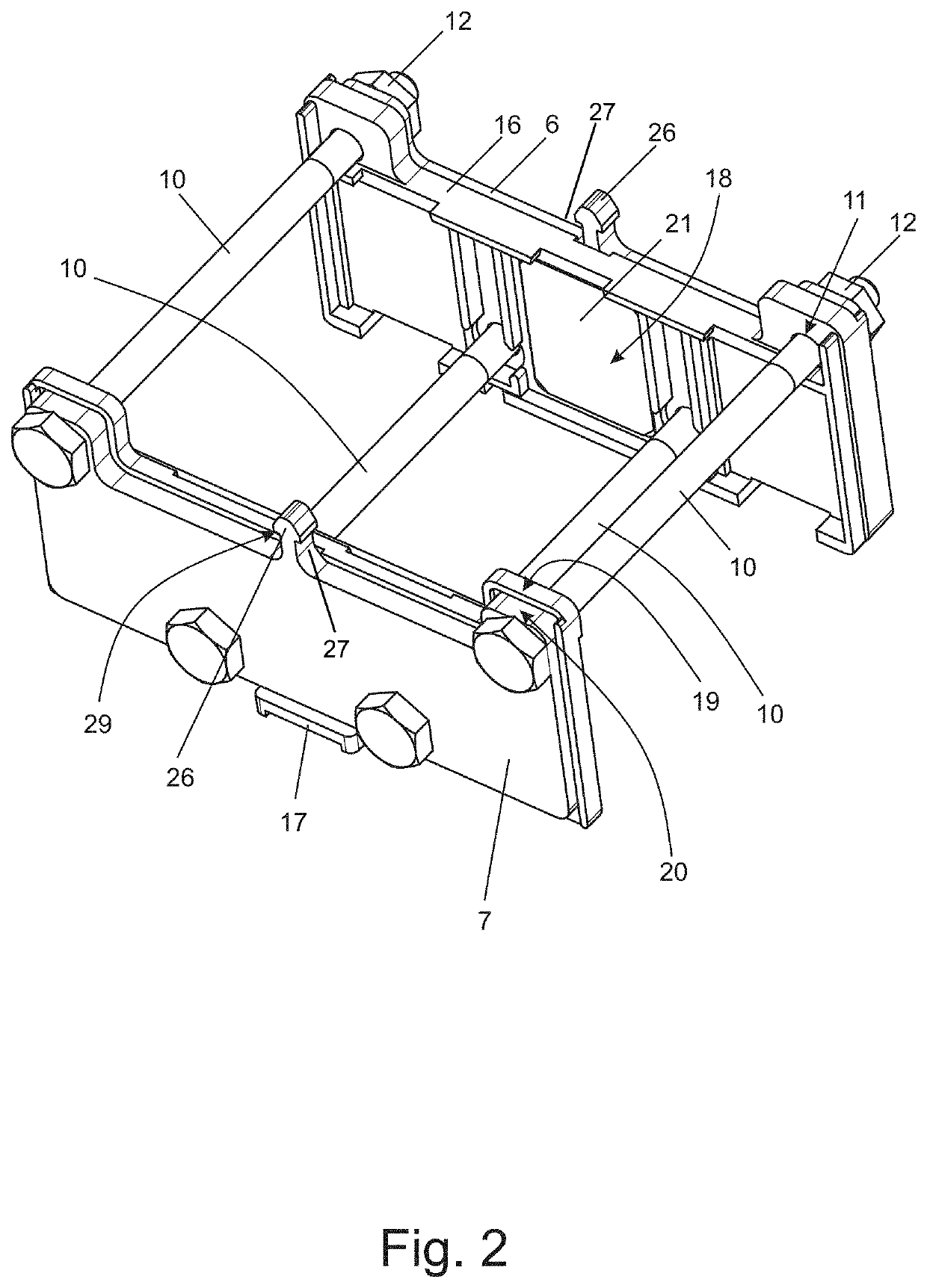
[0035]FIG. 1 shows an exploded view of a surge protection device 1 with three stack spark gaps 2. In order to influence the ignition behavior of the stack spark gaps 2, the surge protection device 1 comprises an ignition switch 5. The stack spark gaps 2 are arranged between a first electrically conductive clamping element 6 and a second electrically conductive clamping element 7, whereby the two clamping elements 6, 7 are arranged opposite to one another on the front sides 8 of the stack spark gaps 2. The clamping elements 6, 7 are connected to one another by connecting elements 9, which are also electrically conductive...


PUM


Abstract

A surge protection device with stack spark gaps, whereby a stack spark gap is formed from multiple electrodes and insulating elements that are arranged between the electrodes, with an ignition switch for influencing the ignition behavior of the stack spark gaps, with a first electrically conductive clamping element and with a second electrically conductive clamping element, whereby the clamping elements are arranged on opposite sides of the stack spark gaps, with at least one connecting element by which the clamping elements are connected to one another, and with connection elements for electrical connection of the stack spark gaps.

Description

BACKGROUND OF THE INVENTIONField of the Invention[0001]The invention relates to a surge protection device with stack spark gaps, whereby a stack spark gap is formed from multiple electrodes and insulating elements that are arranged between the electrodes, with an ignition switch for influencing the ignition behavior of the stack spark gaps, with a first electrically conductive clamping element and with a second electrically conductive clamping element, whereby the clamping elements are arranged opposite to the front sides of the stack spark gaps, with a connecting element, by which the clamping elements are connected to one another, and with connection elements for electrical connection of the stack spark gaps.Description of the Related Art[0002]Surge protection devices are known in a wide variety of designs from the state of the art and are used for protecting electrical devices or lines against surges, which can be caused by, for example, lightning strikes or defects in technical ...

Claims


Application Information

Patent Timeline
IPC IPC(8): H02H9/06H01R4/38
CPCH01R4/38H02H9/06H01T4/02H01T4/04H01T4/06H01T4/16F16B2/12H01T4/18H01T4/20
Inventor MEYER, THOMASSAGEBIEL, HANNESTRACHTE, KARSTEN
Owner PHOENIX CONTACT GMBH & CO KG
Why Eureka
Try Eureka