Blow molding machine

Inactive Publication Date: 2005-08-02
KRUPP KAUTEX MASCHINENBAU GMBH
View PDF28 Cites 16 Cited by
  • Summary
  • Abstract
  • Description
  • Claims
  • Application Information

AI Technical Summary

Benefits of technology

[0038]Compared to conventional hydraulic drives, the blow mold machine according to the invention with electric direct drives offers a considerably enhanced repeating accuracy for defined travel points; the machine has a high flexibility and is ready for immediate use in view of the quick stabilization of the operating state, as there is no need for a start-up period and run-off phase. There are no thermal energy losses and substantially no energy consumption is encountered during the crucial operating phase, namely the force-intensive clamping of the blow mold halves. This is advantageously realized by the brake of the drive mot

Problems solved by technology

However, when special applications are involved such as, e.g., a production

Method used


Image

  • Blow molding machine
  • Blow molding machine
  • Blow molding machine

Examples


Embodiment Construction

[0045]Throughout all the Figures, same or corresponding elements are generally indicated by same reference numerals.

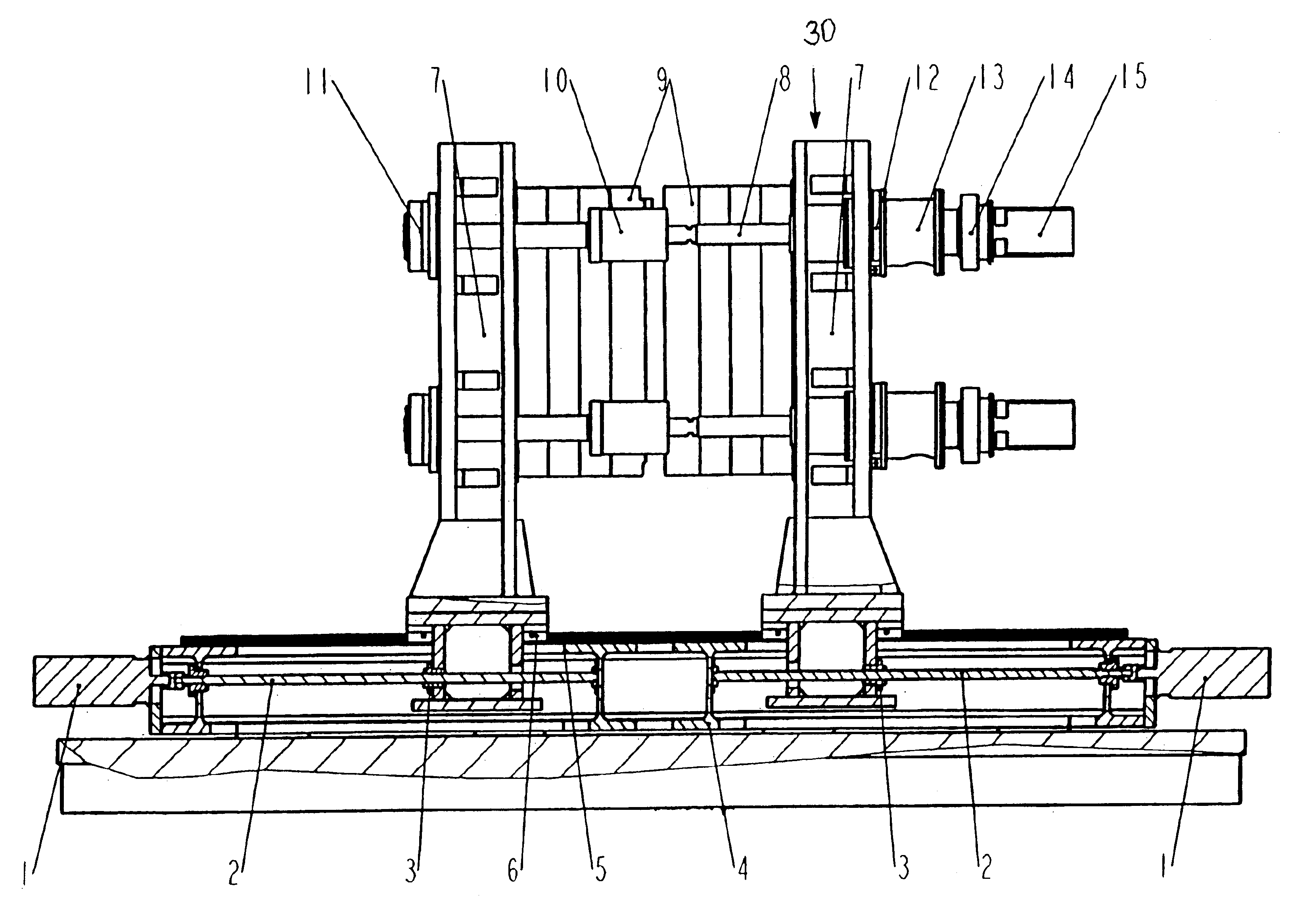
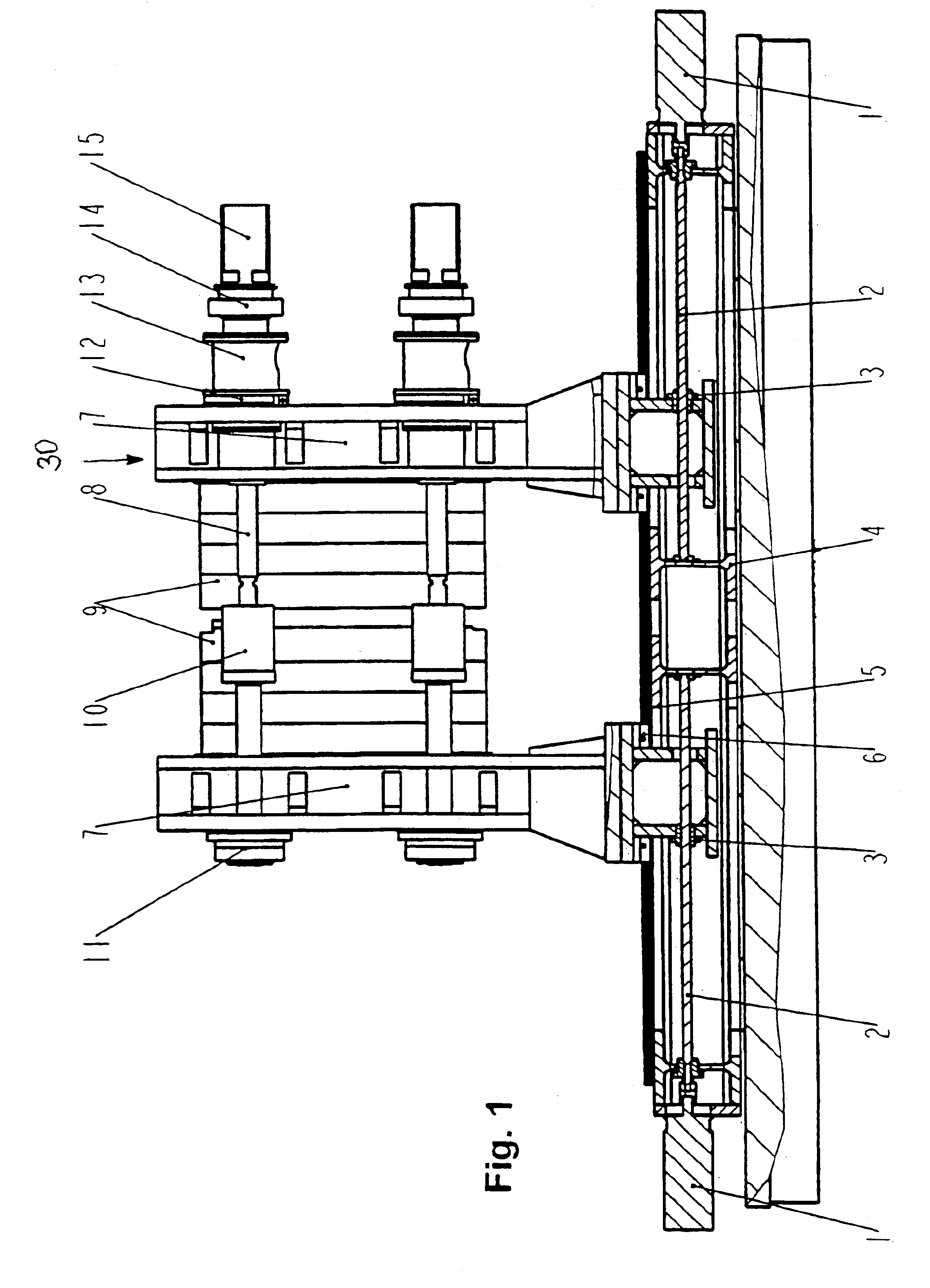
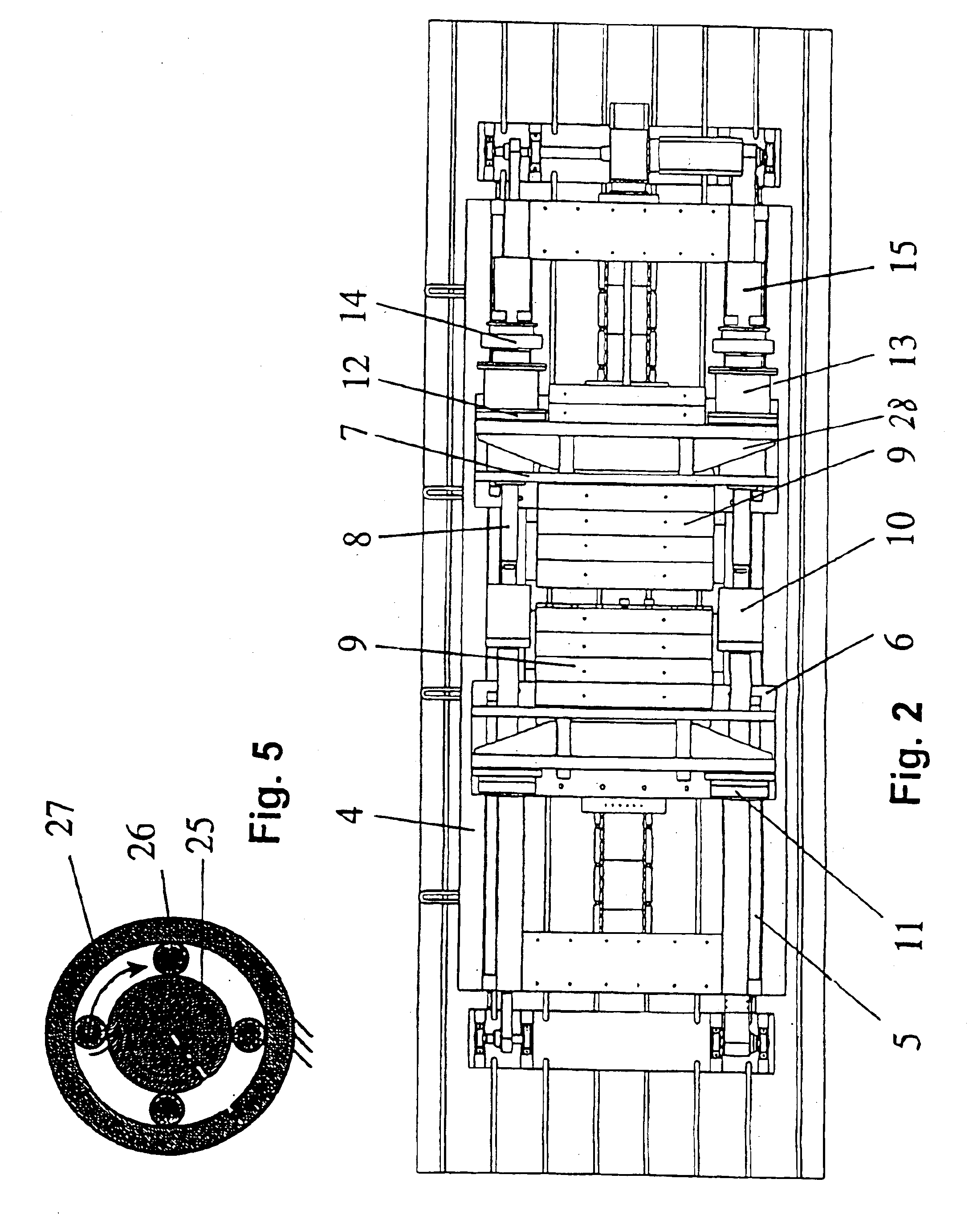
[0046]Turning now to the drawing, and in particular to FIG. 1, there is shown a side view of a blow molding machine according to the invention, including a superstructure, generally designated by reference numeral 30 and comprising the moving parts, and a substructure, generally designated by reference numeral 30 for mounting of the superstructure upon a base frame and four ribbed metal sheets. The superstructure 30 has an active side (right hand side of FIG. 1) and a passive side (left hand side of FIG. 1), each including a mold carrier having two mold mounting plates 7 in parallel relationship. The mold mounting plates 7 of each mold carrier support a mold half 9 and are connected to form a large-area, box-shaped carrier frame (welded construction). The respectively outer ones of the plates 7 (FIG. 2) are hereby configured in rigid manner by horizontal webs 28. The m...


PUM

PropertyMeasurementUnit
Forceaaaaaaaaaa
Pressureaaaaaaaaaa
Displacementaaaaaaaaaa

Abstract

A blow-molding machine for producing blow-molded hollow bodies from a thermoplastic material, includes two blow-mold halves which can be horizontally displaced and provided with separate drive units for a transport drive and for the sequence of movements of the mold closing and locking device to open and close the blow mold halves. Conventional blow-molding machines are still equipped with hydraulic drives at least for the mold closing and locking device. In order to provide a blow-molding machine that can for example be operated under clean-room conditions, the drive unit of the blow-molding machine according to the invention is configured for the clamping elements of the mold closing and locking device as an electromotive direct drive with a spindle drive and a spindle mechanism with recirculating rollers.

Description

CROSS-REFERENCES TO RELATED APPLICATIONS[0001]This application is a continuation of prior filed copending PCT International application no. PCT / EP00 / 08792, filed Sep. 8, 2000.[0002]This application claims the priority of German Patent Application Ser. No. 299 19 885.5, filed Nov. 11, 1999, pursuant to 35 U.S.C. 119(a)-(d), the subject matter of which is incorporated herein by reference.BACKGROUND OF THE INVENTION[0003]The present invention relates to a a blow molding machine for making blow-molded hollow bodies of thermoplastic material, having two blow mold halves traveling horizontally and equipped with separate drive units for the transport drive and for the movement sequences of the mold closing and locking device in order to implement an opening and closing of the blow mold halves.[0004]A blow molding machine of the construction involved here is disclosed, for example, from the printed publication DE 34 16 871 C2 (to Mauser). The separate drives of this conventional blow moldin...

Claims


Application Information

Patent Timeline
IPC IPC(8): B29C33/22B29C49/56B29C49/00
CPCB29C33/22B29C49/56B29C49/5607
Inventor LANGOS, PETERHAMLISCHER, WOLFGANGGEILEN, JOHANNESHOLBACH, MARKUSSCHMITT, WOLFGANGKIEFER, ERICHFRIEDRICHS, KARSTENWEILAND, OLAF
Owner KRUPP KAUTEX MASCHINENBAU GMBH
Why Eureka
Try Eureka