

Fuel cell system installed in vehicle
- Summary
- Abstract
- Description
- Claims
- Application Information
AI Technical Summary
Benefits of technology
Problems solved by technology
Method used
Image



Examples
first embodiment
A. First Embodiment
A1. Fuel Cell System Configuration
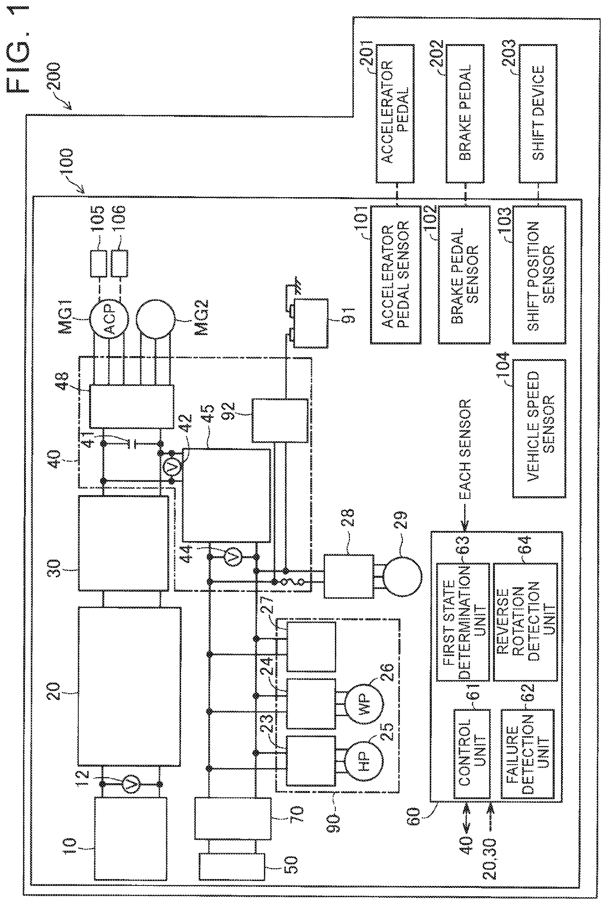
[0016]FIG. 1 is a schematic configuration diagram showing a fuel cell system 100 according to an embodiment of the present disclosure. The fuel cell system 100 is provided in a vehicle 200. As illustrated in FIG. 1, the fuel cell system 100 is provided with a fuel cell 10 and a secondary battery 50 serving as electric power supply sources for a load, a fuel cell converter 20 (hereinafter also referred to as a “FDC 20”), a fuel cell (FC) relay circuit 30, a power control unit 40 (hereinafter, also referred to as a “PCU 40”) including a secondary battery converter 45 (hereinafter, also referred to as a “BDC 45”), a control device 60, a secondary battery relay circuit 70, an auxiliary machine 90, an auxiliary battery 91, an auxiliary machine inverter 28, an air conditioner 29, an air compressor MG1 and a drive motor MG2 each serving as a load.
[0017]The fuel cell 10 is a cell in which hydrogen and oxygen, serving as reaction gases, ar...
second embodiment
B. Second Embodiment
[0045]FIG. 3 shows a limp-home traveling control process according to a second embodiment. The second embodiment differs from the first embodiment in that the second embodiment is provided with the process of step S80, step S82, step S84, and step S86 between step S60 and step S90 in FIG. 2 of the first embodiment. Since the configuration of the fuel cell system 100 and the vehicle 200 of the second embodiment and the other steps in the limp-home traveling control are the same, description thereof will be omitted.
[0046]After supplying the reactive current to the air compressor MG1 in step S60, the control unit 61 determines in step S80 whether the continuous application time from when the reactive current is started to be supplied to the air compressor MG1 is equal to or more than a first time T1 that is predetermined in advance. The continuous application time is an elapsed time after the reactive current is applied in step S40, for example. The first time T1 is...
PUM
 Abstract
Description
Claims
Application Information