Flow Rate Regulating Device and Control Method of Flow Rate Regulating Device

a flow rate regulating device and flow rate technology, which is applied in the direction of operating means/releasing devices of valves, engine diaphragms, diaphragm valves, etc., can solve the problems of particle problems, the purity of fluid cannot be kept high, and the fluid inlet and the central axis of the diaphragm needle are not matched, so as to accurately regulate the flow rate of liquid

Active Publication Date: 2021-08-19
SURPASS IND
View PDF0 Cites 1 Cited by
  • Summary
  • Abstract
  • Description
  • Claims
  • Application Information

AI Technical Summary

Benefits of technology

[0027]According to the control method of the flow rate regulating device of the aspect of the present disclosure, it is possible to inhibit the generation of the particles when the assembly errors or dimensional errors of the members constituting the valve body section and the members constituting the valve seat section are generated, and it is also possible to accurately regulate the fl

Problems solved by technology

However, when a positioning accuracy during the installation of the drive unit and the diaphragm needle in the housing and dimensional accuracy of each component are not sufficient, the central axis of the fluid inlet and the central axis of the diaphragm needle are not matched.
The particles are mixed as impurities in a fluid, and hence, purity of the fluid cannot be kept to be high.
In particular, when a chemical solution for a semiconductor manufacturing apparatus or a high-purity liquid such as pure water is handled as the fluid, problems of the particles become noticeable.
On the other hand, as a result of study by the inventors, it has been found t

Method used


Image

  • Flow Rate Regulating Device and Control Method of Flow Rate Regulating Device
  • Flow Rate Regulating Device and Control Method of Flow Rate Regulating Device
  • Flow Rate Regulating Device and Control Method of Flow Rate Regulating Device

Examples


Embodiment Construction

[0043]A description of example embodiments follows.

[0044]The teachings of all patents, published applications and references cited herein are incorporated by reference in their entirety.

[0045]Hereinafter, preferable embodiments of the present disclosure will be described in detail with reference to the drawings. Note that the embodiments described below are preferable specific examples of the present disclosure, and are therefore technically preferably variously limited. Furthermore, similar components are denoted with similar reference signs through respective drawings and detailed description thereof is appropriately omitted.

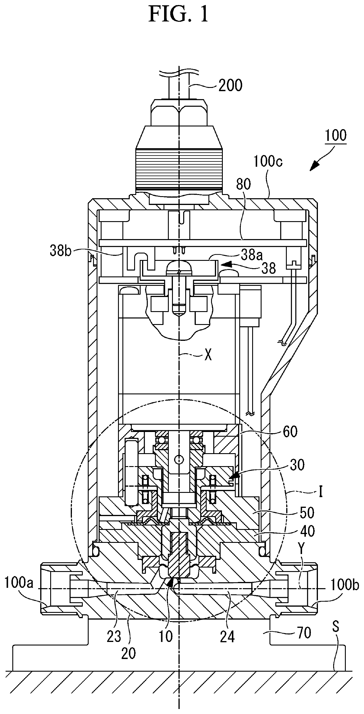
[0046]Hereinafter, an embodiment of the present disclosure will be described with reference to FIG. 1. FIG. 1 is a partially longitudinal cross-sectional view showing a flow rate regulating device 100 of the present embodiment. The flow rate regulating device 100 of the present embodiment is a device that regulates a flow rate of a liquid flowing inside from a...


PUM


Abstract

Provided is a flow rate regulating device including a valve body section having a flat valve body surface; a main body section including a valve chamber, an inflow channel, an outflow channel, and a communication channel; a valve seat section having a flat valve seat surface provided around an inflow opening; a regulation mechanism that moves the valve body section along an axis to regulate a distance between the valve body surface and the valve seat surface; and a control unit that controls the regulation mechanism so that the valve body section moves in a movement range in which the valve body surface and the valve seat surface maintain a non-contact state, wherein a channel cross-sectional area of the communication channel is smaller than each of a channel cross-sectional area of the inflow channel and a channel cross-sectional area of the outflow channel.

Description

RELATED APPLICATION[0001]This application claims priority under 35 U.S.C. § 119 or 365 to Japanese, Application No. 2020-025352, filed Feb. 18, 2020. The entire teachings of the above application are incorporated herein by reference.BACKGROUND1. Technical Field[0002]The present disclosure relates to a flow rate regulating device and a control method of the flow rate regulating device.2. Description of Related Art[0003]There has heretofore been known a flow rate regulating valve that controls a flow rate of a fluid (e.g., see Publication of Japanese Patent No. 5144880).[0004]The flow rate regulating valve disclosed in the Publication of Japanese Patent No. 5144880 transmits a drive force of a motor to a diaphragm needle as a valve body, and regulates a gap between a fluid inlet and the diaphragm needle inserted into the fluid inlet, to regulate the flow rate of the fluid.[0005]When assembling a flow rate regulating device disclosed in Publication of Japanese Patent No. 5144880, it is...

Claims


Application Information

Patent Timeline
IPC IPC(8): F16K41/10F16K31/50F16K31/04F16K7/12
CPCF16K41/103F16K7/12F16K31/047F16K31/508F16K7/16F16K1/52F16K1/42F16K1/36F16K31/04H01L21/67017
Inventor ANDO, YUICHISEKINE, SATOSHI
Owner SURPASS IND
Why Eureka
Try Eureka