Touch display device

a display device and touch technology, applied in the field of displays, can solve the problems of touch sensitivity reduction and touch sensitivity reduction, and achieve the effect of linearity and sensitivity of the touch function of the display devi

Active Publication Date: 2021-12-23
HUIZHOU CHINA STAR OPTOELECTRONICS TECHNOLOGY CO LTD
View PDF0 Cites 0 Cited by
  • Summary
  • Abstract
  • Description
  • Claims
  • Application Information

AI Technical Summary

Benefits of technology

[0025]A pressure difference between the sealed cavity and external atmospheric pressure is utilized to decrease a gap value of the sealed cavity, at the same time, the gap value of the sealed cavity always remains constant during use of the touch display device, linearity and sensitivity of touch function of the touch display device meeting product requirements can be ensured.

Problems solved by technology

However, when the touch layer is connected to the display panel by air gap bonding, during use of the touch display device, it is difficult to keep gap sizes between the touch layer and the display panel constant, therefore, touch signals of the touch layer become unstable, resulting in reduction of touch sensitivity.
In conventional touch display devices, the touch layer is connected to the display panel by air gap bonding, it is difficult to keep the gap sizes between the touch layer and the display panel constant, therefore, touch signals of the touch layer become unstable, resulting in the reduction of touch sensitivity.

Method used


Image

  • Touch display device
  • Touch display device
  • Touch display device

Examples


Embodiment Construction

[0040]The description of following embodiment, with reference to the accompanying drawings, is used to exemplify specific embodiments which may be carried out in the present application. The directional terms mentioned in the present application, such as “up”, “down”, “front”, “back”, “left”, “right”, “inside”, “outside”, and “side surface” etc., only refer to the directions in attached drawings. Therefore, the directional terms are used to illustrate and help understand this disclosure, but not used to limit this disclosure. In the figures, the same reference numbers are configured to represent elements with similar structures.

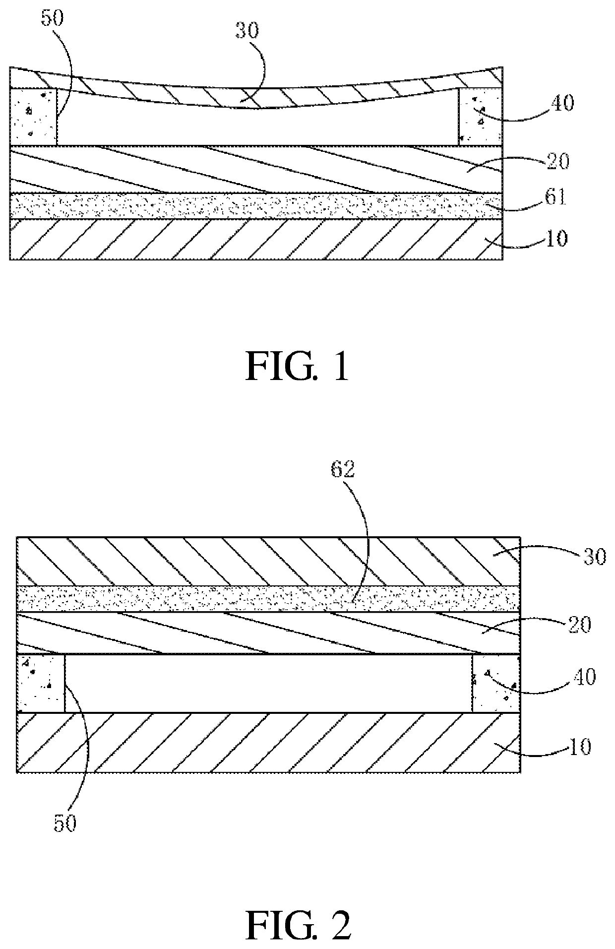
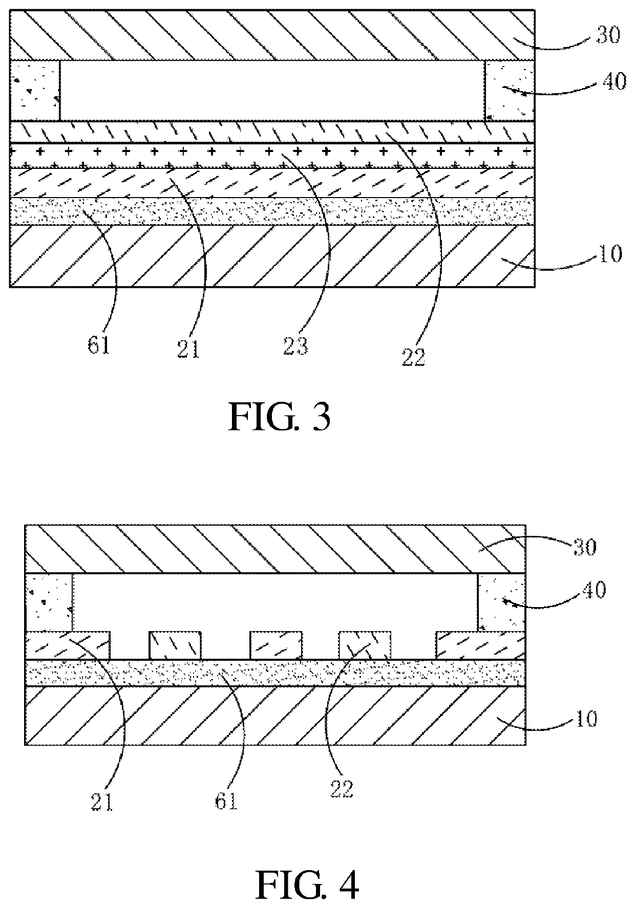
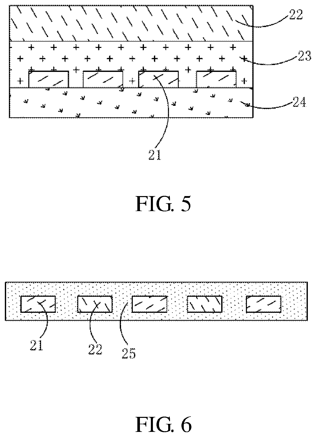
[0041]The present application aims to solve the technical problem that in conventional touch display devices, the touch layer is connected to the display panel by frame adhesive, wherein due to inconsistent gap sizes between the touch layer and the display panel, therefore touch signals of the touch layer become unstable, resulting in reduction of touch sensi...


PUM

PropertyMeasurementUnit
thicknessaaaaaaaaaa
air pressure intensityaaaaaaaaaa
air pressureaaaaaaaaaa

Abstract

A touch display device is disclosed, including a display panel and a touch layer, a sealant disposed between the touch layer and the display panel, the sealant, the touch layer, and the display panel forming a sealed cavity. An air pressure intensity inside the sealed cavity is less than a preset value.

Description

BACKGROUND OF INVENTIONField of Invention[0001]This application relates to technical field of displays, and particularly relates to a touch display device.Description of Prior Art[0002]Currently, in touch display devices, a touch layer and a display panel are generally connected by air gap bonding or optical bonding. As to large-size display panels, in order to reduce production costs, air gap bonding is mostly applied in connection of the touch layer and the display panel in this industry.[0003]However, when the touch layer is connected to the display panel by air gap bonding, during use of the touch display device, it is difficult to keep gap sizes between the touch layer and the display panel constant, therefore, touch signals of the touch layer become unstable, resulting in reduction of touch sensitivity.[0004]In conventional touch display devices, the touch layer is connected to the display panel by air gap bonding, it is difficult to keep the gap sizes between the touch layer ...

Claims


Application Information

Patent Timeline
Patent Type & Authority Applications(United States)
IPC IPC(8): G06F3/041G06F3/044
CPCG06F3/0412G06F3/044
Inventor HUANG, DONGCHENCHENG, CHINGYUAN
Owner HUIZHOU CHINA STAR OPTOELECTRONICS TECHNOLOGY CO LTD
Why Eureka
Try Eureka