Three-stage electronic ballast for metal halide lamps

a technology of electronic ballast and metal halide lamps, which is applied in the direction of instruments, light sources, electrical equipment, etc., can solve the problems of low efficiency of electronic ballast, and high peak value of inductor current, so as to improve efficiency, reduce power loss, and increase the duration of electronic ballast

Inactive Publication Date: 2005-02-15
LIGTEK ELECTRONICS
View PDF3 Cites 138 Cited by
  • Summary
  • Abstract
  • Description
  • Claims
  • Application Information

AI Technical Summary

Benefits of technology

Accordingly, the present invention discloses a three-stage electronic ballast for supplying steady power source for a metal halide lamp. The electronic ballast comprises a power factor correction circuit including a step-up converter, a DC step-down co...

Problems solved by technology

This results in high peak values of the inductor currents and therefore high power loss in the circuit.
And, consequently, the electronic bal...

Method used


Image

  • Three-stage electronic ballast for metal halide lamps
  • Three-stage electronic ballast for metal halide lamps
  • Three-stage electronic ballast for metal halide lamps

Examples


Embodiment Construction

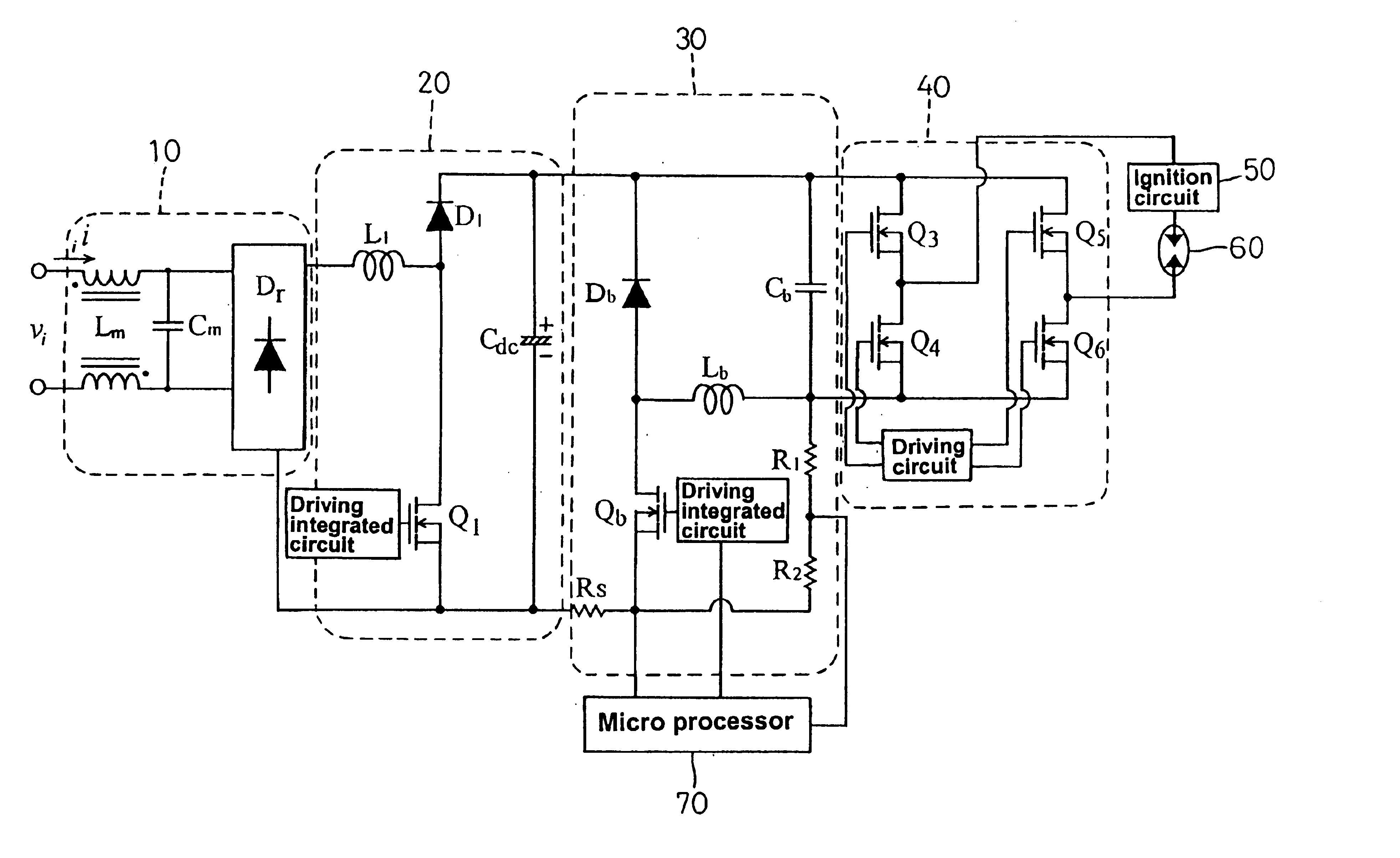
Referring to FIG. 1, a circuitry diagram according to the present invention utilizes a filter and rectification circuit 10 to filter and rectify an input commercial electric voltage Vi for suppressing electromagnetic disturbances. The voltage signal is then amplified by a step-up converter 20 and supplied to a step-down converter 30 for current control. The step-down converter 30 comprises a transistor switch Qb, a diode Db, an inductor Lb, a capacitor Cb and resistors R1, R2. A full-bridge DC-AC converter 40 is disposed after the step-down converter 30, which further includes transistor switches Q3, Q4, Q5 and Q6. A high-voltage ignition circuit 50, in series connection with a metal halide lamp 60, is disposed at the AC output terminal of the full-bridge DC-AC converter 40 for discharging the metal halide lamp 60.

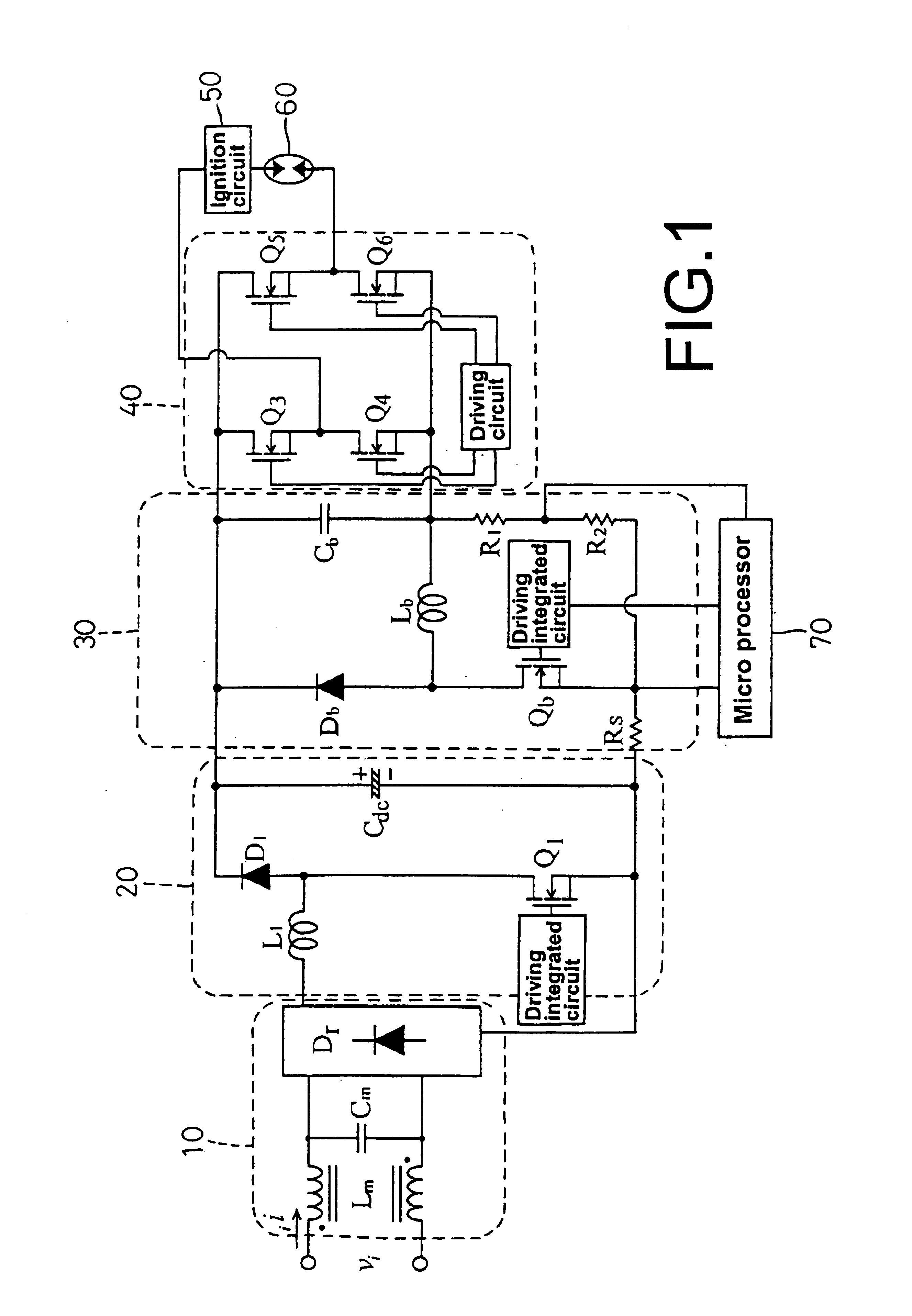
Referring to FIGS. 1 and 2, the principle of the circuitry according to the present invention is specified as follows. A commercial electric voltage Vi is applied to a fil...


PUM


Abstract

A three-stage electronic ballast for metal halide lamps mainly comprises a step-up converter, a step-down converter and a full-bridge DC-AC converter, wherein the step-down converter operates an inductor in a continuous boundary current mode to achieve reducing power loss and enhancing efficiency. Equipped with a micro processor, the electronic ballast further possesses the function of power regulation. The electronic ballast can be added with various protective functions without complex control circuits and sensing elements, thereby becoming a high-quality and low-cost electronic ballast for metal halide lamps.

Description

BACKGROUND OF THE INVENTION1. Field of the InventionThe present invention relates to electronic ballasts for metal halide lamps, and more particularly to an electronic ballast for metal halide lamps having a three-stage structure. The three-stage electronic ballast for metal halide lamps mainly comprises a step-up converter, a step-down converter and a full-bridge DC-AC converter, wherein the step-down converter operates an inductor in a continuous boundary current mode to achieve reducing power loss and enhancing efficiency. Equipped with a micro processor, the electronic ballast further possesses the function of power regulation. The electronic ballast can be added with various protective functions without complex control circuits and sensing elements, thereby becoming a high-quality and low-cost electronic ballast for metal halide lamps.2. Description of the Prior ArtHigh-intensity gas-discharging lamps are widely used as light sources for indoor or outdoor illumination. Given it...

Claims


Application Information

Patent Timeline
IPC IPC(8): H05B41/28H05B41/288
CPCH05B41/2886
Inventor LIN, TSAI-FULIANG, TSORNG-JUUYEN, HAU-CHEN
Owner LIGTEK ELECTRONICS
Why Eureka
Try Eureka