Chromatic dispersion compensating fiber

a technology of chromatic dispersion and fiber, which is applied in the field of optical fiber transmission, can solve the problems of not providing a significant reduction in the absolute value of residual dispersion, and the difficulty of dispersion compensation,

Inactive Publication Date: 2009-01-27
DRAKA COMTEQ BV
View PDF14 Cites 148 Cited by
  • Summary
  • Abstract
  • Description
  • Claims
  • Application Information

AI Technical Summary

Benefits of technology

[0016]Therefore, a need exists for a system to compensate chromatic dispersion with which it is possible to strongly reduce—and perhaps even cancel—the absolute value of the residual chromatic dispersion on a given spectral band.
[0018]With reference to FIG. 1, it is noted that the association of two dispersion compensating fibers (i.e., DCF connection to the optical transmission system) makes it possible to strongly reduce the absolute value of the maximum residual dispersion for low DOS and to cancel the maximum residual dispersion for transmission systems having higher DOS values.

Problems solved by technology

The smaller the DOS ratio of a transmission fiber, the more difficult it is to compensate the dispersion and the dispersion slope with a DCF.
Consequently, this disclosure does not provide a significant reduction in the absolute value of the residual dispersion.

Method used


Image

  • Chromatic dispersion compensating fiber
  • Chromatic dispersion compensating fiber
  • Chromatic dispersion compensating fiber

Examples


example 1

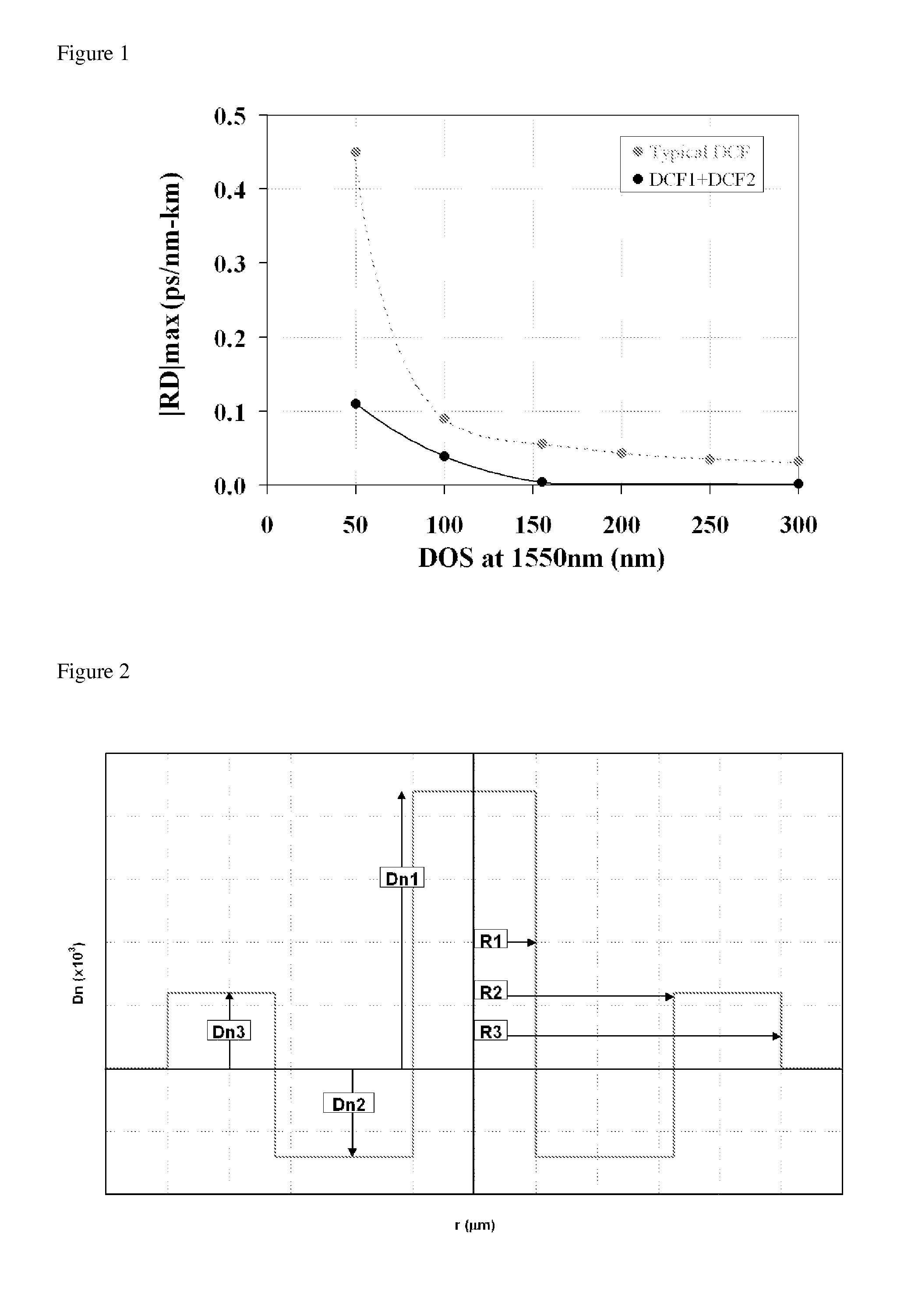
[0066]In this first example, the line fiber of the transmission system has a DOS value of 50 nm. As explained previously, these line fibers are used in long-haul transmissions with high bit rates, and so it is important to be able to compensate the chromatic dispersion accumulated in these fibers while respecting this DOS value. The line fiber in this first example is the fiber marketed by Corning under the trademark LEAF, and the prior art compensating fiber mentioned in Table 1-I corresponds to a typical fiber having a DOS value of 50 nm required for compensating the dispersion of such a line fiber. It is noted, however, in Table 1-I and in FIG. 1 the compensation of a line fiber having a DOS as low as 50 nm using a single compensating fiber induces a high absolute value of residual dispersion on the edges of the spectral band under consideration. It can be seen in Table 1-I that this absolute value of maximum residual dispersion is reduced by one quarter when using two associated...

example 2

[0070]In this second example, the line fiber of the transmission system has a DOS of 100 nm. The line fiber in this first example is the line fiber marketed by OFS under the trade name TRUEWAVE® RS, and the prior art compensating fiber mentioned in Table 2-I corresponds to a typical fiber having the DOS value of 100 nm required to compensate the dispersion of such a line fiber. Table 2-I shows that the absolute value of the residual dispersion can be reduced by half when using two associated compensating fibers according to the present invention as compared with the use of a single compensating fiber.

[0071]In this example, two different second compensating fibers DCF2 and DCF2b were associated with a first compensating fiber DCF1, and a third compensating fiber DCF3 was associated with fibers DCF1 and DCF2. It is particularly noted that it is possible to choose a compensating fiber DCF2b with a positive dispersion slope S even though the line fiber has a positive dispersion slope. T...

example 3

[0079]In this third example, the line fiber of the transmission system has a DOS of 154 nm. The line fiber in this third example is the fiber marketed under the trade name TERALIGHTÓ by Draka Comteq, and the prior art compensating fiber mentioned in Table 3-I corresponds to a typical fiber having a DOS value of 154 nm required for compensating the dispersion of such a line fiber. Table 3-I shows that the absolute value of the residual dispersion can be practically cancelled when using two associated compensating fibers according to the present invention as compared with the use of a single compensating fiber.

[0080]

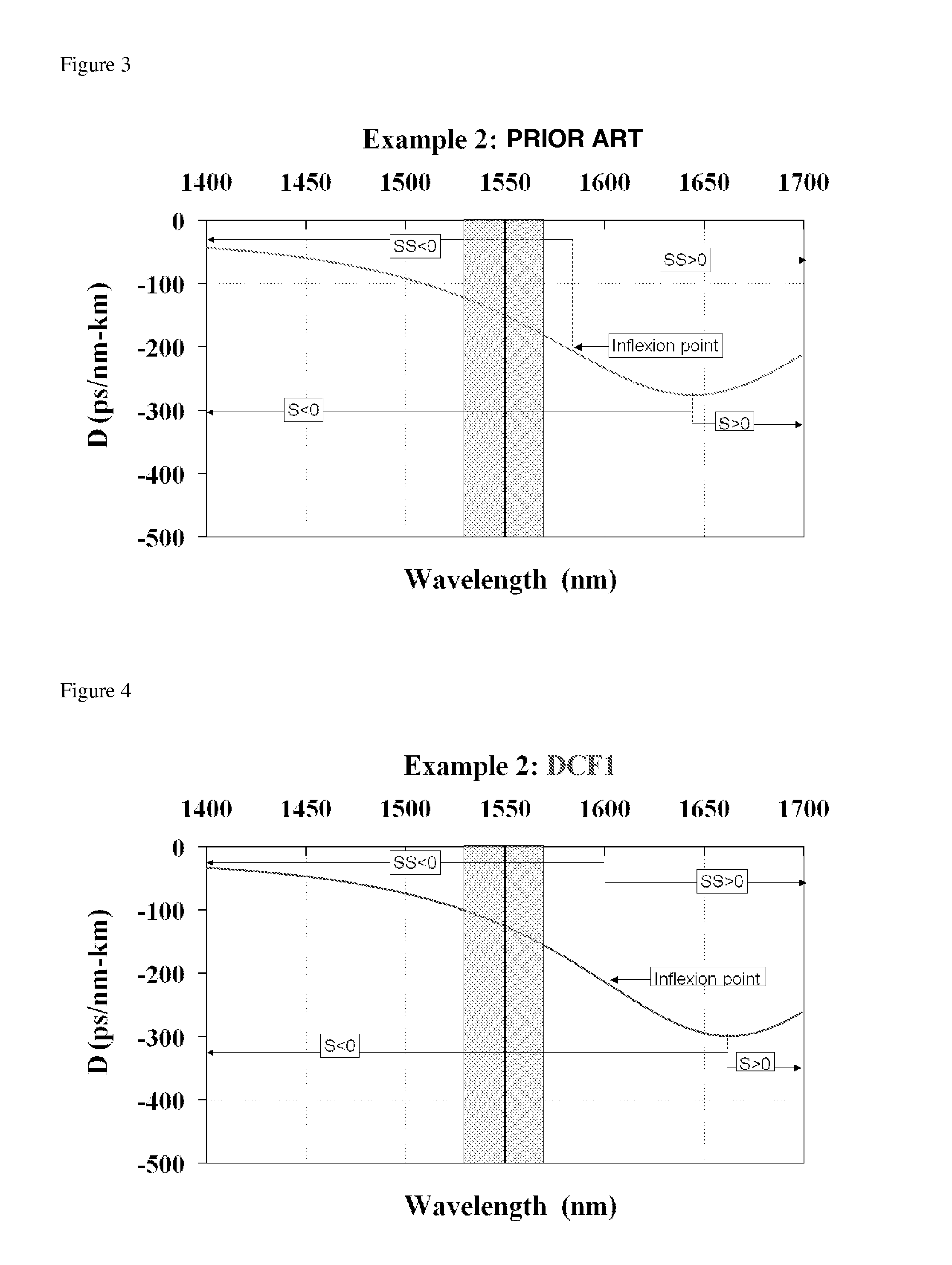
TABLE 3-IRDmaxSSS(1530-1570Dps / ps / DOSLnm)Example 3ps / nm-kmnm2-kmnm3-kmnmkmps / nm-kmLine fiber8.000.0520154100DCF−150−0.97−0.00491545.33−0.052prior artDCF1−100−0.77−0.00381303.47−0.002DCF2−250−1.400.00701791.81
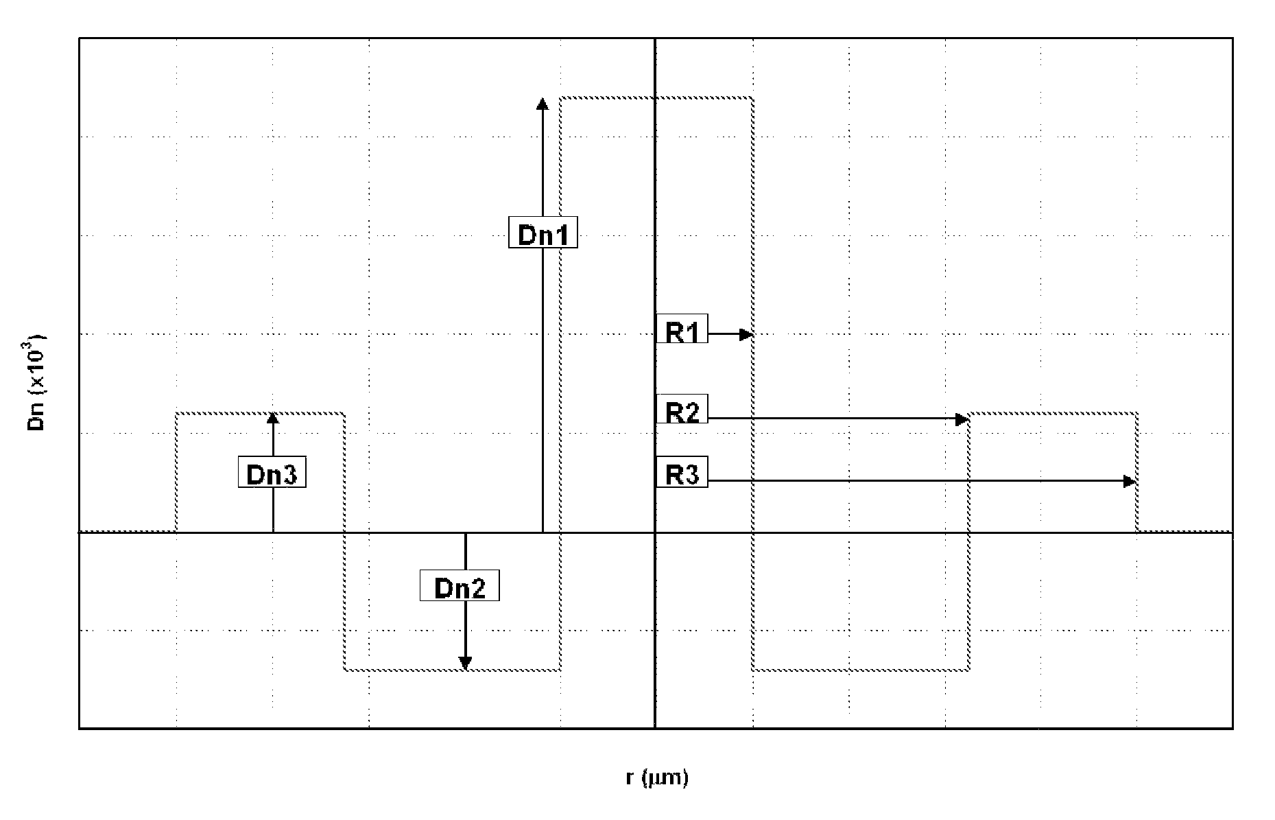
[0081]

TABLE 3-IIDn1Dn2Dn3r1r2r3Example 3(×10−3)(×10−3)(×10−3)(μm)(μm)(μm)DCF120.5−11.96.01.734.397.12DCF231.6−11.74.61.243.567.11


PUM


Abstract

Disclosed are an improved system and a related method for compensating the chromatic dispersion of a given length of a transmission fiber over a given spectral band by employing at least two chromatic dispersion compensating fibers that, with respect to the slope of the slope of the chromatic dispersion (SSi), have values of opposite signs.

Description

CROSS-REFERENCE TO PRIORITY APPLICATION[0001]This application hereby claims the benefit of pending French Application No. 06 / 09616 (filed Nov. 3, 2006 at the French Patent Office), which is hereby incorporated by reference in its entirety.FIELD OF THE INVENTION[0002]The present invention relates to the area of optical fiber transmission and, more specifically, to the compensation of the chromatic dispersion, of the chromatic dispersion slope, and of the slope of the chromatic dispersion slope in optical fiber transmission systems.BACKGROUND OF THE INVENTION[0003]For optical fibers, the index profile is generally qualified in relation to the tracing of the graph plotting the function that associates the refractive index with the fiber radius. Conventionally, the distance r to the center of the fiber is shown along the abscissa, and the difference between the refractive index and the refractive index of the fiber cladding is shown along the ordinate axis. The index profile is therefor...

Claims


Application Information

Patent Timeline
Patent Type & Authority Patents(United States)
IPC IPC(8): G02B6/02G02B6/36H04B10/00H04B10/12H04J14/02H04B10/2525
CPCH04B10/25253
Inventor BIGOT-ASTRUC, MARIANNEDE MONTMORILLON, LOUIS-ANNEMOLIN, DENISSILLARD, PIERRE
Owner DRAKA COMTEQ BV
Why Eureka
Try Eureka