Speed reducer and speed reducer-equipped motor

a technology of speed reducer and gear reducer, which is applied in the direction of gearing details, transportation and packaging, gearing, etc., can solve the problem of irregular movement of revolving gear

Active Publication Date: 2022-03-31
DENSO CORP
View PDF11 Cites 0 Cited by
  • Summary
  • Abstract
  • Description
  • Claims
  • Application Information

AI Technical Summary

Benefits of technology

[0007]In consideration of the circumstances described above, a first object of the present disclosure is to provide a speed reducer and a speed reducer-equipped motor that may assure strength of an engaging portion of a revolving gear that engages with a member that restricts spinning of the revolving gear, and a second object of the present disclosure is to provide a speed reducer and a speed reducer-equipped motor that may suppress irregularity of movements of the revolving gear.
[0012]A speed reducer and speed reducer-equipped motor according to the present disclosure provide an excellent effect in that strength may be assured of an engaging portion of a revolving gear that engages with a member that restricts spinning of the revolving gear. The speed reducer and speed reducer-equipped motor according to the present disclosure provide a further excellent effect in that movements of the revolving gear becoming irregular may be suppressed.

Problems solved by technology

Moreover, in the speed reducer of the speed reducer-equipped motor recited in Patent Document 1, if a contact state between the revolving gear and the member that restricts spinning of the revolving gear, a contact state between the member that restricts spinning of the revolving gear and a member that supports the restricting member, or the like changes, movement of the revolving gear may become irregular.

Method used


Image

  • Speed reducer and speed reducer-equipped motor
  • Speed reducer and speed reducer-equipped motor
  • Speed reducer and speed reducer-equipped motor

Examples


Embodiment Construction

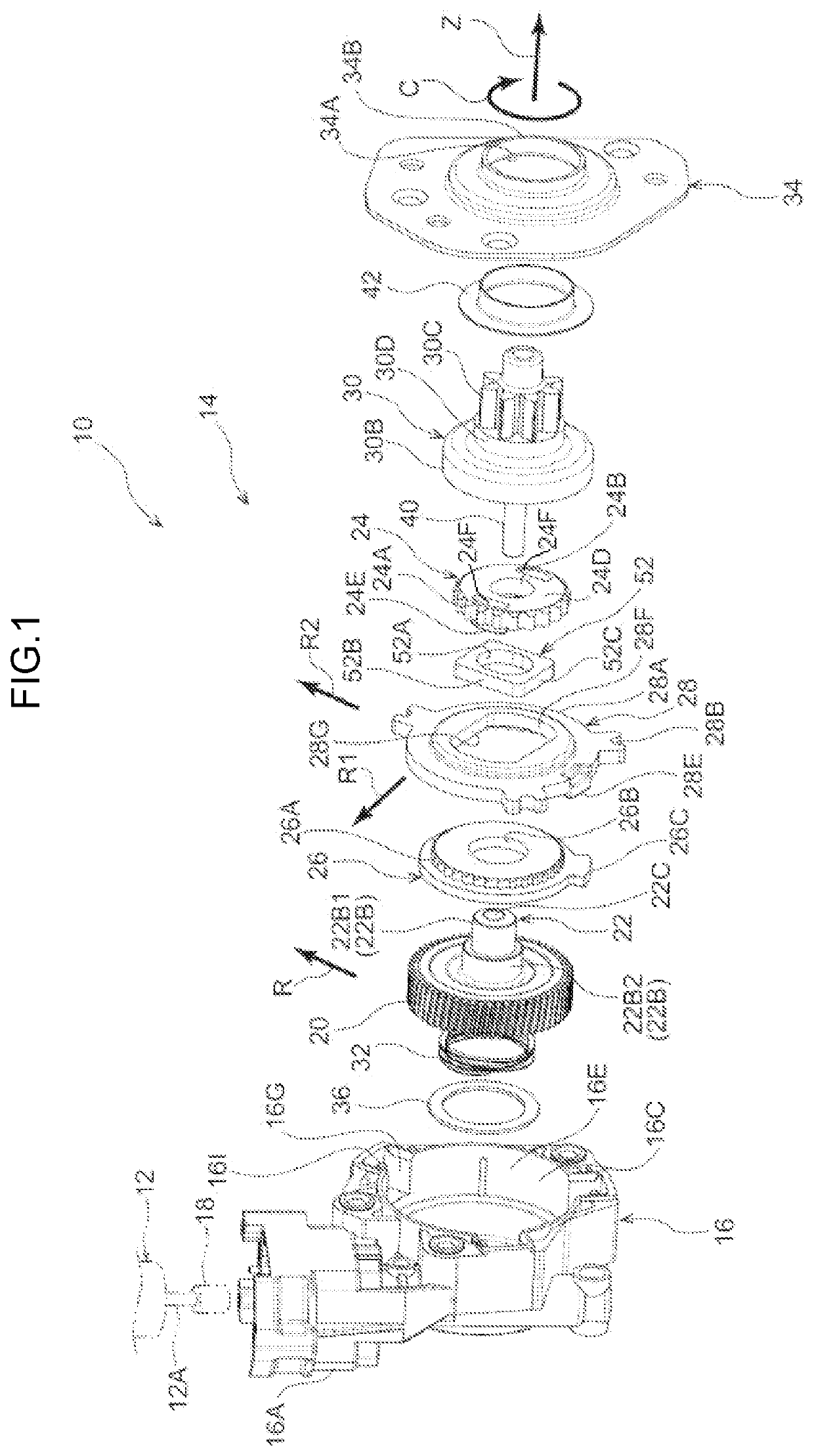
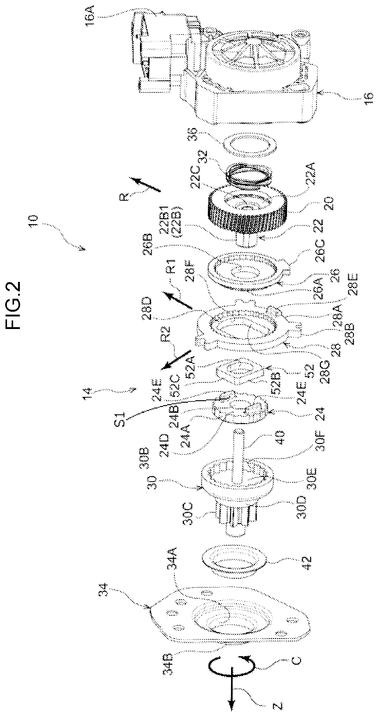
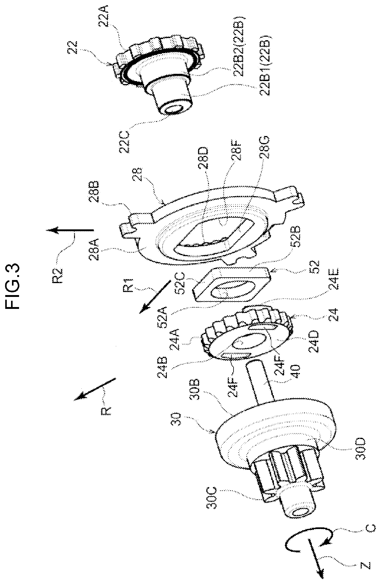
[0040]A speed reducer-equipped motor 10 according to an exemplary embodiment of the present disclosure is described using FIG. 1 to FIG. 4B. The direction of an arrow Z, the direction of an arrow R and the direction of an arrow C, which are shown where appropriate in the drawings, indicate, respectively, one side in a rotation axis direction of a pinion gear 30C, which is an output gear, the outer side in a rotation radial direction of the pinion gear 30C, and one side in a rotation circumferential direction of the pinion gear 30C. The opposite side to the direction of arrow Z, the opposite side to the direction of arrow R and the opposite side to the direction of arrow C indicate, respectively, the other side in the direction of the rotation axis of the pinion gear 30C that is the output gear, the inner side in the rotation radial direction, and the other side in the rotation circumferential direction. Where simply an axis direction, a radial direction and a circumferential directi...


PUM


Abstract

A speed reducer includes a helical gear, an eccentric shaft and a slider plate. The speed reducer also includes a transmission gear and an output gear body. The transmission gear is supported at a first support part, transmission gear spinning is restricted by engagement with the slider plate, and the transmission gear revolves by the helical gear rotating with the eccentric shaft. The output gear body rotates by the transmission gear revolving. The transmission gear includes a pair of restricting protrusions protruding toward the slider plate side. The restricting protrusions have engaging surfaces that touch the slider plate wherein the engaging surfaces oppose the slider plate in a radial direction of the transmission gear. Surfaces at opposite sides of the restricting protrusions from the slider plate are formed, as seen in the axis direction of the transmission gear, to be convex to the opposite sides thereof from the slider plate.

Description

CROSS-REFERENCE TO RELATED APPLICATIONS[0001]The present application is based on Japanese Patent Application Nos. 2019-178402, 2019-178403 and 2019-178404, filed on Sep. 30, 2019, and the disclosures thereof are incorporated into the present specification.TECHNICAL FIELD[0002]The present disclosure relates to a speed reducer and a speed reducer-equipped motor.BACKGROUND ART[0003]Patent Document 1 discloses a speed reducer-equipped motor provided with a speed reducer that reduces a speed of rotation of a motor. The speed reducer recited in this document is provided with: a worm gear fixed to a rotation axis of the motor; a worm wheel meshing with the worm gear; a gear that is revolved by rotation of the worm wheel, in a state in which spinning of the revolving gear is restricted; and an output shaft that is rotated by rotary force being transmitted thereto in accordance with the revolution of the revolving gear. A member that restricts spinning of the revolving gear is provided betwe...

Claims


Application Information

Patent Timeline
Patent Type & Authority Applications(United States)
IPC IPC(8): F16H1/32H02K7/116
CPCF16H1/32F16H2001/323H02K7/116F16H57/08F16H55/17F16H2001/327F16H2057/02082B60N2/02253F16H2001/326
Inventor MARUO, KAZUKISAKAI, MASAHITOSHIMIZU, FUMIHIRO
Owner DENSO CORP
Why Eureka
Try Eureka