
Feed mechanism

a technology of a feeding mechanism and a feeding position, which is applied in the direction of stereoscopic photography, instruments, gearing, etc., can solve the problems of feed irregularity, deterioration of the feed position of the moving body, etc., and achieve the effect of suppressing feed irregularity

Active Publication Date: 2021-06-22
FUJIFILM CORP
View PDF14 Cites 0 Cited by
  • Summary
  • Abstract
  • Description
  • Claims
  • Application Information

AI Technical Summary

Benefits of technology

[0005]An object of the invention is to obtain a feed mechanism that can suppress feed irregularity caused by the inclination of a nut of a feed screw.
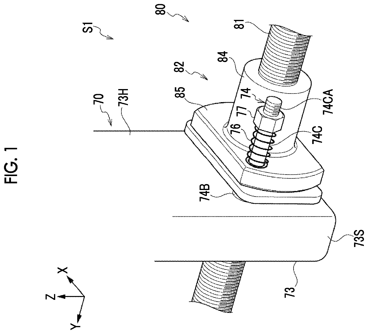
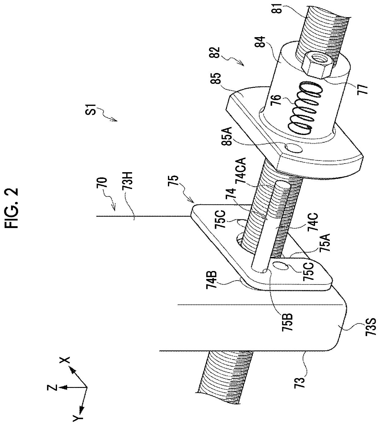
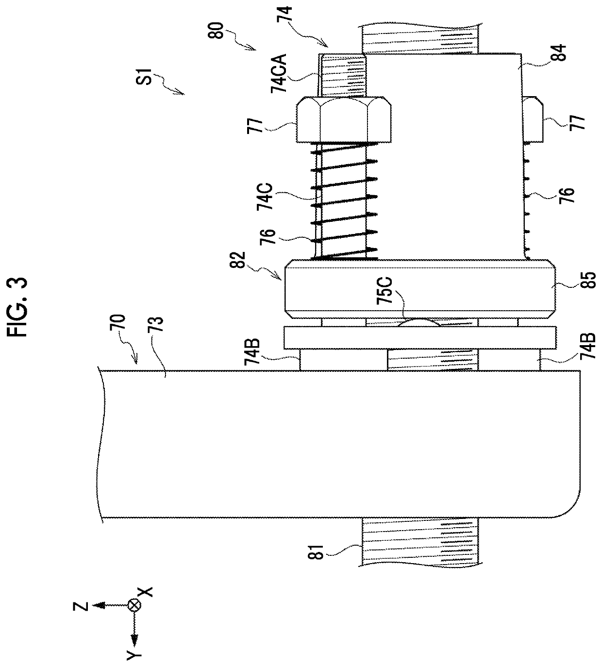
[0007]In this aspect, the feed mechanism includes the feed screw and the moving body. Further, the nut is moved on the screw shaft by the rotation of the screw shaft, so that the moving body is moved in the direction of the screw shaft. Here, the moving body or the nut includes the convex portion, and the moving body is pushed by the nut through only the convex portion and the inclination of the moving body with respect to the nut is allowed in a case in which the moving body is moved by the movement of the nut. For this reason, even in a case in which the nut is inclined during the movement of the nut on the screw shaft, the influence of the inclination of the nut on the moving body is suppressed. Accordingly, feed irregularity caused by the inclination of the nut of the feed screw can be suppressed.
[0015]In this aspect, it is possible to suppress lateral irregularity in a case in which an image is read by the scanning unit.
[0017]In this aspect, the feed mechanism further comprises the elastic body and the elastic body makes an elastic force act in a direction where the nut and the moving body come into contact with each other at the convex portion. For this reason, since a state in which the nut and the moving body are in contact with each other at the convex portion is likely to be kept, it is possible to suppress an impact against the moving body that is caused in a case in which the nut comes into contact with the moving body from a state in which the nut is not in contact with the moving body.
[0021]In this aspect, the two rotation-preventing shafts, which are provided with the elastic bodies, are present and are provided so as to be symmetric with respect to the center of the nut. For this reason, since the elastic forces of the elastic bodies can be made to act on the nut and the moving body in balance, the relative postures of the nut and the moving body are stabilized.
[0024]According to the invention, it is possible to suppress feed irregularity caused by the inclination of a nut of a feed screw.

Problems solved by technology

Accordingly, the accuracy of the feed position of the moving body deteriorates and feed irregularity occurs.

Method used


Image

  • Feed mechanism
  • Feed mechanism
  • Feed mechanism

Examples


modification example

[0093

[0094]Next, a sub-scanning mechanism S2 according to a modification example will be described with reference to FIGS. 10 and 11. The same portions as those of the embodiment are denoted by the same reference numerals as those of the embodiment, and the detailed description thereof (also including common actions) will be appropriately omitted.

[0095]An aspect where the scanning unit 70 is pushed by the nut 82 through the convex portions 75C in a case in which the scanning unit 70 is to be moved toward one side in the Y direction has been described in the embodiment. In contrast, in the modification example, the scanning unit 70 is adapted to be pushed by a nut (an opposite nut 182) through only convex portions (opposite convex portions 175C) not only in a case in which the scanning unit 70 is to be moved toward one side in the Y direction but also in a case in which the scanning unit 70 is to be moved toward the other side in the Y direction.

[0096]As shown in FIGS. 10 and 11, the...


PUM


Abstract

A feed mechanism, which is capable of suppressing feed irregularity caused by the inclination of a nut of a feed screw, is obtained. A feed mechanism (sub-scanning mechanism) includes a feed screw that includes a screw shaft and a nut and a moving body, and the nut is moved on the screw shaft by a rotation of the screw shaft, so that the moving body is moved in the direction of the screw shaft. The inclination of the moving body with respect to the nut is allowed in a case in which the moving body is moved by a movement of the nut.

Description

CROSS-REFERENCE TO RELATED APPLICATIONS[0001]The present application claims priority under 35 U.S.C. § 119 to Japanese Patent Application No. 2017-165263, filed on Aug. 30, 2017. Each of the above application(s) is hereby expressly incorporated by reference, in its entirety, into the present application.BACKGROUND OF THE INVENTION1. Field of the Invention[0002]The present invention relates to a feed mechanism.2. Description of the Related Art[0003]A feed mechanism that linearly moves a moving body by a feed screw including a screw shaft and a nut has been known in the past (for example, JP2009-92129A).SUMMARY OF THE INVENTION[0004]However, a nut may be inclined with respect to a screw shaft in a case in which the nut is moved on the screw shaft. For this reason, in a case in which the moving body is fixed to the nut as in the technique disclosed in JP2009-92129A, the inclination of the nut is transmitted to the moving body as it is. Accordingly, the accuracy of the feed position of ...

Claims


Application Information

Patent Timeline
Patent Type & Authority Patents(United States)
IPC IPC(8): F16H25/20F16H25/24G03B42/02G03B42/08G02B21/36
CPCF16H25/24F16H25/20G03B42/02G03B42/08F16H2025/204F16H2025/2445G02B21/362
Inventor OTA, KOHEI
Owner FUJIFILM CORP
Learn More