Printing apparatus and printing method

a printing apparatus and printing method technology, applied in printing, printing, power drive mechanisms, etc., can solve the problems of not being able to obtain desired tone, not being able to discharge the discharged per unit area from the recording head, and affecting the quality of image, so as to suppress the occurrence of gloss irregularities. , the effect of high quality imag

Active Publication Date: 2016-07-07
SEIKO EPSON CORP
View PDF0 Cites 0 Cited by
  • Summary
  • Abstract
  • Description
  • Claims
  • Application Information

AI Technical Summary

Benefits of technology

[0006]An advantage of some aspects of the invention is to provide a printing technology t

Problems solved by technology

However, in the apparatus disclosed in JP-A-2006-150788, gloss irregularities in band units may occur.
For example, ink to be discharg

Method used


Image

  • Printing apparatus and printing method
  • Printing apparatus and printing method
  • Printing apparatus and printing method

Examples


first embodiment

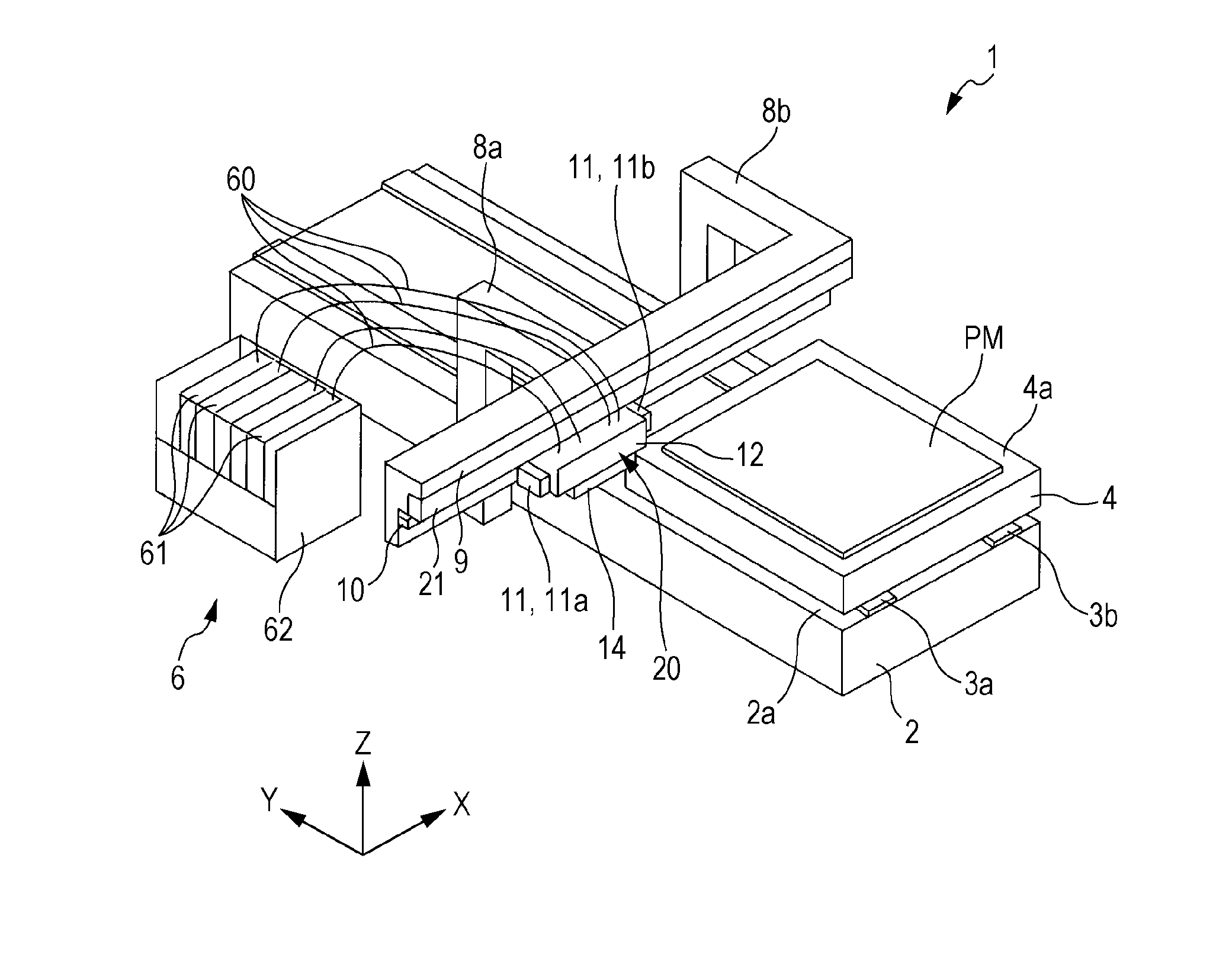
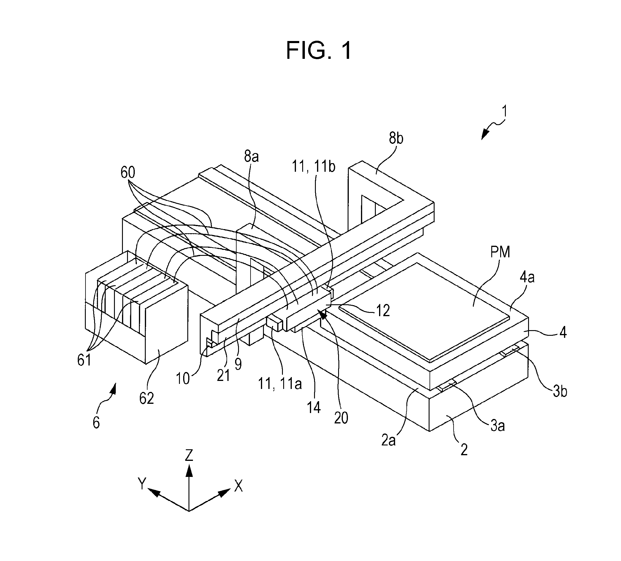
[0032]FIG. 1 is a drawing showing an ink jet printing apparatus that is the ink jet printing apparatus according to the invention. FIG. 2 is a schematic drawing showing a head and electrical configuration of the ink jet printing apparatus shown in FIG. 1. The printing apparatus 1 includes an ink set that including ultraviolet ray curable inks with four mutually differing colors, a print head that discharges ink from the ink set as droplets, and an ultraviolet ray radiating section that radiates ultraviolet rays. A control section that controls the driving of the various members is provided. A specific description is provided below.

[0033]As shown in FIG. 1, a base 2 formed in a rectangular parallelepiped is provided in the ink jet printing apparatus 1. In the embodiment, the length direction of the base 2 is the Y-axis direction, and the direction intersecting the Y-axis direction is the X-axis direction.

[0034]A pair of guide rails 3a and 3b extending in the Y-axis direction is provi...

second embodiment

[0067]In this way, in the second embodiment, the line images A21 and B21 are continuously formed while performing backward printing and the forward printing in this order on the second area AR2. At this point in time, the head 20 is positioned at a position separated from the printing medium PM in the (+X) axis direction. In this state, by the Y-axis motor being driven by the control section 5, the stage 4 moves in the (−Y) axis direction, and the stage 4 is positioned so that the first area AR1 of the printing medium PM is positioned vertically below the reciprocation path of the head 20, and is at a position shifted in the (+Y) direction by one dot further in the Y-axis direction than during the first scanning operation. Thus, when the printing preparation for the line image B11 is completed, as shown in FIG. 12, ink is discharged from the black nozzle 141 of the print head 14 toward the surface of the first area AR1 based on the printing data provided from the control section 5 w...


PUM


Abstract

A printing apparatus includes a head that discharges ink to a printing region, and causes ink dots formed on the printing region to be cured to form a line image in a first direction, and a movement section that that causes the printing medium to move relative to the head in a second direction intersecting the first direction, in which the printing region is divided into a plurality of areas in the second direction, and the movement section alternately switches the area in which the line image is formed by the head between the plurality of areas while causing the printing medium to relatively move.

Description

BACKGROUND[0001]1. Technical Field[0002]The present invention relates to a printing apparatus and a printing method that print an image in a printing region on a printing medium.[0003]2. Related Art[0004]In the related art, a printing apparatus is proposed, which performs band printing while intermittently transporting a printing medium in a transport direction by a predetermined delivery width (so-called one band). For example, in the apparatus disclosed in JP-A-2006-150788, band printing is performed while scanning using a recording head three times with respect to one band. The apparatus achieves suppression of gloss irregularities by randomly thinning the ink discharge from the recording head in the final scan of the three scans.[0005]However, in the apparatus disclosed in JP-A-2006-150788, gloss irregularities in band units may occur. Even though gloss irregularities are suppressed in each band by randomly thinning the ink discharge, image quality of the image may be lowered by...

Claims


Application Information

Patent Timeline
IPC IPC(8): B41J25/00
CPCB41J11/002B41J25/001B41J2/2114B41J2/2132B41J11/00214
Inventor SUGAI, KEIGOOTAKE, MASAHISAHAMA, YOSHIKAZU
Owner SEIKO EPSON CORP
Why Eureka
Try Eureka