Continuously variable transmission apparatus

a transmission apparatus and variable technology, applied in mechanical devices, transportation and packaging, gearing, etc., can solve the problems of generating time delay, taking time to complete introduction of sufficient quantity of pressure oil, etc., to reduce the degree of incongruous feeling, reduce the time delay in the mode switching operation from the high speed mode to the low speed mode, and reduce the degree of incongruity

Inactive Publication Date: 2005-08-23
NSK LTD
View PDF21 Cites 131 Cited by
  • Summary
  • Abstract
  • Description
  • Claims
  • Application Information

AI Technical Summary

Benefits of technology

[0093]In view of the above-mentioned circumstances of the prior art, it is an object of the invention to provide a continuously variable transmission apparatus which can restrict the occurrence of a transmission shock in the mode switching operation.
[0096]According to a third aspect of the present invention, there is provided a continuously variable transmission apparatus, comprising: arm input shaft connected to a drive source and rotationally driven by the drive source; an output shaft for taking out power obtained based on the rotational movement of the input shaft; a toroidal-type continuously variable transmission including an input side disk, an output side disk, power rollers interposed between the input side and output side disks so as to be swingly rotatable, and trunnions for supporting the power rollers; a transmission control valve for shifting the trunnions; a feedback mechanism for transmitting the shift amounts of the trunnions to the transmission control valve for feedback so that a transmission ratio between the input and output disks provide a target value; a planetary gear mechanism including three elements, that is, a sun gear, a carrier and a ring gear; a first power transmission system for transmitting the power input to the input shaft to the output shaft through the toroidal-type continuously variable transmission; a second power transmission system for transmitting the power input to the input shaft to the output shaft without passing through the toroidal-type continuously variable transmission, the power to be transmitted through the first power transmission system and the power to be transmitted through the second power transmission system being joined to two of the three elements of the planetary gear mechanism, the remaining one of the three elements being connected to the output shaft; a clutch mechanism, when advancing a vehicle, for switching over a first mode on the low speed side and a second mode on the high speed side to each other; and, a control device, when switching over the first and second modes to each other, for controlling the transmission control valve simultaneously with the switching operation of the clutch mechanism within the time during which the clutch mechanism is switched, thereby restricting variations in the transmission ratio of the toroidal-type continuously variable transmission.
[0098]According to the above-structured continuously variable transmission apparatus of the present invention, the time delay in the mode switching operation from the high speed mode to the low speed mode can be reduced and an increase in the rotation speed of an engine in the mode switching operation can be restricted, thereby being able to reduce the degree of an incongruous feeling that is given to the driver.
[0099]That is, since, when switching the high speed mode over to the low speed mode, the timing for signaling for connecting the low speed clutch is set earlier than the timing for signaling for cutting off the connection of the high speed clutch, it is possible to reduce the time from the disconnection of the high speed clutch to the connection of the low speed clutch.
[0100]As a result of this, in the mode switching operation from the high speed mode to the low speed mode, there can be reduced the time during which the high speed and low speed clutches are both disconnected, which can reduce an increase in the number of rotations of the engine in the present mode switching operation and thus can reduce the degree of an incongruous feeling that is given to the driver.

Problems solved by technology

Firstly, the time delay is caused by the fact that it takes some time to complete the full-stroke movements of the pistons incorporated in the high speed and low speed oil pressure cylinders 90, 91.
This shifting operation is carried out by introducing pressure oil into the oil pressure cylinders 90, 91; however, due to resistance within the pipes used to introduce the pressure oil, it inevitably takes time to complete introduction of a sufficient quantity of pressure oil.
This gives rise to the above-mentioned generation of the time delay.
During the above time delay, since the engine serving as the power source is not connected (or is imperfectly connected) to the drive wheel, the power cannot be transmitted from the engine to the drive wheel.
Also, in case where the clutch is connected after the rotation speed of the engine increases for an instant, there is a possibility that the whole of the power transmission system including the continuously variable transmission apparatus can be vibrated, which also gives the driver an incongruous feeling.
There is a possibility that such incongruous feeling can increase especially in the switching operation from the high speed mode to the low speed mode.
Therefore, in case where even a slight degree of transmission shock occurs in the mode switching operation, the drive feels incongruous.
23), in case where, when no transmission instruction is issued in the mode switching operation, the transmission ratio varies greatly to thereby cause a transmission shock, the driver feels badly incongruous.

Method used


Image

  • Continuously variable transmission apparatus
  • Continuously variable transmission apparatus
  • Continuously variable transmission apparatus

Examples


first embodiment

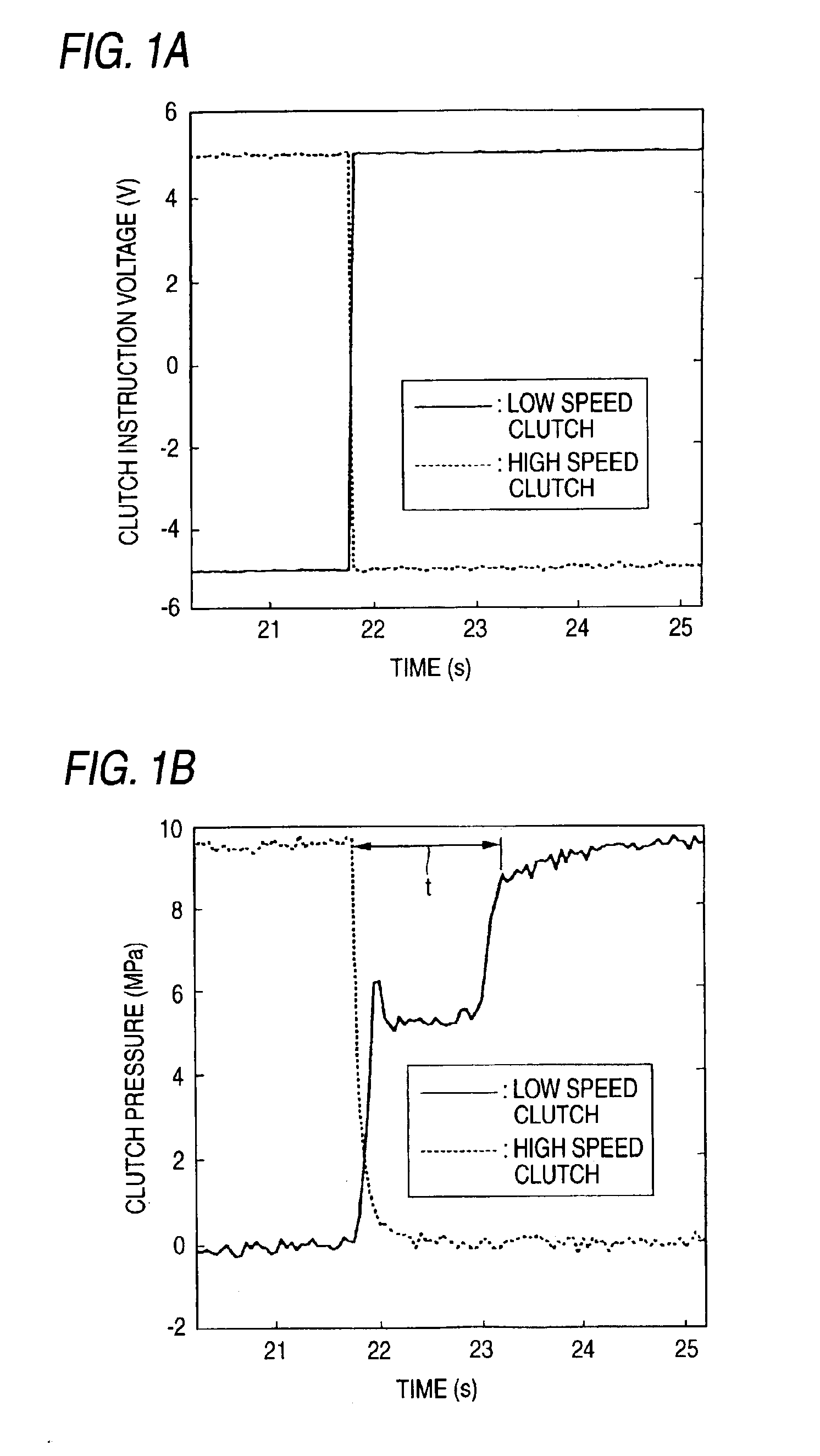
[0124]Now, FIGS. 1A and 1B show a continuously variable transmission apparatus according to the present invention. By the way, according to the present invention, there is provided a continuously variable transmission apparatus in which a toroidal-type continuously variable transmission and a planetary gear mechanism are combined together through a clutch device including a high speed clutch and a low speed clutch; and, the present continuously variable transmission apparatus is characterized in that the timings for signaling for disconnecting and connecting the high speed and low speed clutches are improved to thereby be able to reduce the incongruous feeling that is generated in the mode switching operation from the high speed mode to the low speed mode. The structure of the present continuously variable transmission apparatus, as a whole, is similar to the structure of the test apparatus shown in the previously discussed FIG. 15; and, the more specific structure of the present co...

third embodiment

[0134]Now, description will be given below of a continuously variable transmission apparatus according to the present invention with reference to FIGS. 4 to 8.

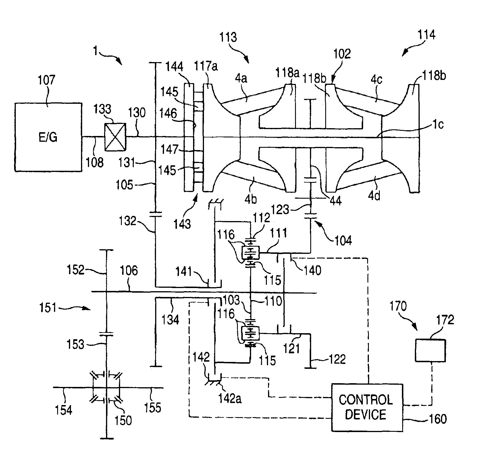
[0135]A continuously variable transmission apparatus shown in FIG. 4, similarly to the continuously variable transmission apparatus shown in FIG. 18, comprises a double cavity type of half toroidal-type continuously variable transmission 102, a planetary gear mechanism 103, a first power transmission mechanism 104, a second power transmission mechanism 105, and a drive shaft 108 which can be rotated by the power of an engine 107. The first power transmission mechanism 104 corresponds to a first power transmission system as set forth in the patent claims of the present invention, while the second power transmission mechanism 105 corresponds to a second power transmission system as set forth in the patent claims of the present invention.

[0136]The toroidal-type continuously variable transmission 102 comprises a first input side d...

fourth embodiment

[0198]By the way, as in the present invention shown in FIG. 9, in the switching operation for switching the low speed mode over to the high speed mode, in case where the transmission control is started slightly after the start of the clutch switching operation, that is, slightly after the start of the torque variation, the variation width in the transmission ratio of the toroidal-type continuously variable transmission 102 can be restricted to a further small range.

[0199]Specifically, in the time of “3 sec.” in the horizontal axis of FIG. 9, the switching operation of the clutches is started and, slightly after the start of the clutch switching operation and just before the time of “4 sec.”, the above-mentioned transmission control is started. And, at the time when the clutch switching operation is ended, the transmission control is ended. As a result of this, the variation width in the transmission ratio of the toroidal-type continuously variable transmission 102 can be reduced fur...


PUM


Abstract

A continuously variable transmission apparatus has clutch device having a low speed clutch; a high speed clutch; and, a controller switching the transmission state into any one of a low speed mode and a high speed mode by connecting any one of the clutches, wherein timings for signaling by the controller for switching the connected and disconnected states of the clutches vary according to the switching directions of the low speed and high speed modes; and, a timing for signaling for connecting the low speed clutch with respect to the moment for signaling for cutting off the connection of the high speed clutch in order to switch the high speed mode over to the low speed mode is set earlier than a timing for signaling for connecting the high speed clutch with respect to the moment for signaling for cutting off the connection of the low speed clutch.

Description

BACKGROUND OF THE INVENTION[0001]1. Field of the Invention[0002]A continuously variable transmission apparatus according to the present invention is used as a transmission unit constituting an automatic transmission for a vehicle or as a transmission for any one of various kinds of industrial mechanical apparatus. Especially, a continuously variable transmission apparatus according to the present invention is developed in order to reduce an incongruous feeling given to a driver when switching a low speed mode and a high speed mode over to each other using a clutch mechanism.[0003]2. Description of the Related Art[0004]As an automatic transmission for a vehicle, such a toroidal-type continuously variable transmission as schematically shown in FIGS. 10 and 11 is known well because it is disclosed in many publications such as patent publications, and it is also enforced currently in part of the vehicle industry. When a toroidal-type continuously variable transmission of this type is in...

Claims


Application Information

Patent Timeline
Patent Type & Authority Patents(United States)
IPC IPC(8): F16H61/06F16H61/66F16H61/664F16H61/08F16H37/08
CPCF16H61/061F16H37/086F16H61/08Y10T477/6217F16H2037/0886F16H2306/44F16H2306/52F16H61/664
Inventor MIYATA, SHINJIHASHITANI, HIDEKI
Owner NSK LTD
Why Eureka
Try Eureka